


08
July 27, 09 K.Okada
A.Miyoshi I.Fujioka
Refer to Revision Record on page 2.
TITLE
fi-6140/fi-6240/fi-6130/fi-6230/fi-614PR
Maintenance Manual
07
Nov.12, 08 K.Okada
T.Anzai
I.Fujioka
Refer to Revision Record on page 2.
CUST.
06
Mar.10, 08 K.Okada
T.Anzai
I.Fujioka
Refer to Revision Record on page 2.
DRAW
No.
P1PA03540-B0XX/6
Rev. DATE DESIGN CHECK APPR. DESCRIPTION
Design
July 27, 2007
K.Okada
CHECK
K.Okada
APPR.
T.Anzai
PFU LIMITED
Page
51
/
257
Section 4-3-1
How to Troubleshoot:
The troubleshooting should be conducted from item number 1 to the last item number in each table.
Continue the troubleshooting until the error is corrected.
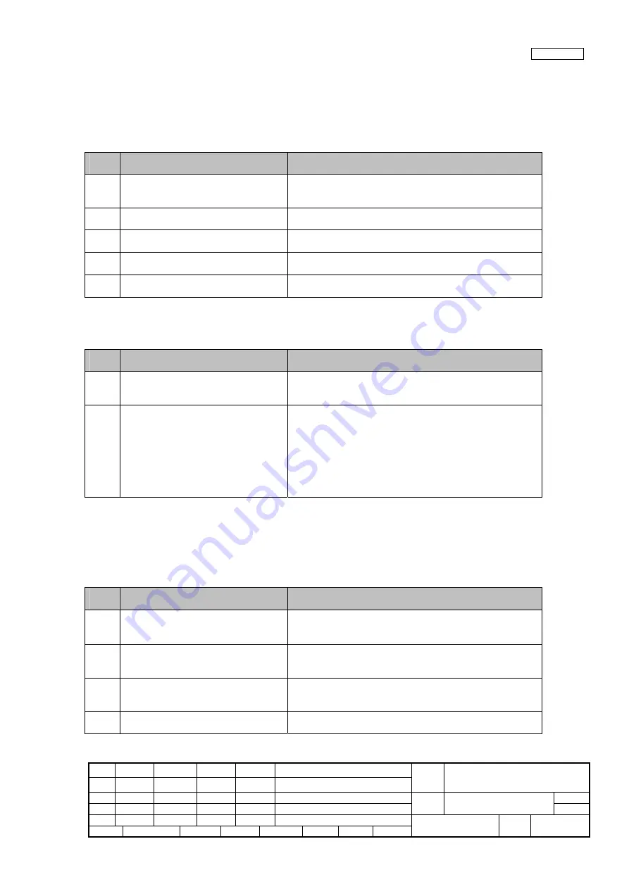
4-3-1 Scanner is not turned ON (Display of the operator panel goes out)
Table 4-3-1
Item
No.
Check items
How/where to check
1
Does the same symptom occur after
turning OFF and ON the scanner?
Press power button of the scanner for more than 2 seconds to
turn it OFF, and after more than 2 seconds elapse, press the
power button to turn the scanner ON.
Are the AC cable and AC Adapter
correctly connected?
---
2
Replace the AC cable and AC Adapter
and see if the error is resolved.
---
3
Replace Panel PCA and see if the error is
resolved.
Refer to Section 5-10-9.
4
Replace Control PCA and see if the error
is resolved.
Refer to Section 5-11.
4-3-2 Scanning does not start
Table 4-3-2
Item
No.
Check items
How/where to check
1
Does the same symptom appear when
turning the scanner ON again?
Press power button of the scanner for more than 2 seconds to
turn it OFF, and after more than 2 seconds elapse, press the
power button to turn the scanner ON.
2
Check the items listed in the right
column.
•
Are the AC cable and AC Adapter correctly connected?
•
Is there documents loaded on ADF paper chute (Chuter
Unit)?
•
Is ADF cover completely closed?
•
Is interface cable correctly connected?
•
Is SCSI ID correctly set?
•
If any temporary error or alarm is indicated, follow the
corresponding troubleshooting.
4-3-3 Scanned image is distorted
Due to loose connection of connectors, cut wire in cables or defective parts, scanned image may have regular or random pattern
distortion on it.
Table 4-3-3
Item
No.
Check items
How/where to check
1
Check the items listed in the right
column.
•
Is interface cable correctly connected?
•
If any temporary error or alarm is indicated, follow the
corresponding troubleshooting.
2
Are the cables between Control PCA and
Optical Unit damaged? Or are the
connectors connected correctly?
ADF front scanning: See Section 5-9-6 for checking.
ADF back scanning: See Section 5-10-4 for checking.
FB scanning: See Section 5-12-5 for checking.
3
Replace Optical Unit and see if the error
is resolved.
ADF front scanning: See Section 5-9-6 for replacement.
ADF back scanning: See Section 5-10-4 for replacement.
FB scanning: See Section 5-12-5 for replacement.
4
Replace Control PCA and see if the error
is resolved.
Refer to Section 5-11.


