


Touch Screens
7-32
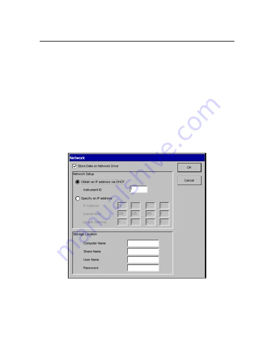
Network Dialog
AAnalyst 200 data can be saved to a stand-alone computer or to a network computer using a
LAN connection. Once a network connection is established, all the analyses result data will
automatically be saved.
To establish connection between a stand-alone computer and the AA200 instrument, follow the
procedure below. It is recommended that you contact your system administrator to setup
connections for network computer.
Stand-Alone Computer
1.
Use a crossover cable (P/N 0941-0061) to connect the AA200 instrument to a computer.
•
Connect the crossover cable to the Ethernet port of the E-Box (see
chapter 5
for
connectors on the E-Box).
•
From the E-Box, run the crossover cable to the Ethernet port of the computer.
2.
From the AA application (Touch Screen) touch the
Tools…
button to access the Tools
dialog.
3.
Touch the
Network…
button on the Tools dialog to access the Network dialog.
Screen 7- 19 Network Dialog
4.
At the top of the Network dialog, click on the
Store Data on Network Drive
check box to
turn the store data function on.
Содержание aanalyst 200
Страница 1: ...AAnalyst 200 User s Guide ...
Страница 6: ......
Страница 7: ...Introduction 1 ...
Страница 8: ......
Страница 18: ...Introduction 1 12 ...
Страница 19: ...Safety Practices 2 ...
Страница 20: ......
Страница 44: ...Safety Practices 2 26 ...
Страница 45: ...Preparing Your Lab 3 ...
Страница 46: ......
Страница 52: ...Preparing Your Lab 3 8 473 mm 650 mm 910 mm 700 mm 760 mm 170 mm Figure 3 1 Outside dimensions of instrument ...
Страница 55: ...AAnalyst 200 User s Guide 3 11 Figure 3 3 Space requirements for the spectrometer system top view ...
Страница 66: ...Preparing Your Lab 3 22 ...
Страница 67: ...System Description 4 ...
Страница 68: ......
Страница 89: ...Installation 5 ...
Страница 90: ......
Страница 107: ...AAnalyst 200 User s Guide 5 19 Setting up the Burner System Figure 5 9 Full view of the AAnalyst 200 Instrument ...
Страница 115: ...Operation of the Instrument 6 ...
Страница 116: ......
Страница 126: ...Operation of the Instrument 6 12 Installing the Burner Mount Assembly Figure 6 6 Installing the burner mount assembly ...
Страница 132: ...Operation of the Instrument 6 18 Figure 6 9 Installing the lamp compartment cover ...
Страница 158: ...Operation of the Instrument 6 44 ...
Страница 159: ...Touch Screens 7 ...
Страница 160: ......
Страница 173: ...AAnalyst 200 User s Guide 7 15 Screen 7 10 Spectrometer Subpage Flame Technique ...
Страница 193: ...AAnalyst 200 User s Guide 7 35 Screen 7 22 Shortcut menu Properties folder appear and select Share this folder option ...
Страница 210: ...Touch Screens 7 52 ...
Страница 211: ...Analyzing Samples 8 ...
Страница 212: ......
Страница 220: ...Analyzing Samples 8 10 Screen 8 4 Display Calibration screen ...
Страница 231: ...AAnalyst 200 User s Guide 8 21 The results are displayed and printed Screen 8 12 Analyze page ...
Страница 244: ...Analyzing Samples 8 34 ...
Страница 245: ...Maintenance 9 ...
Страница 246: ......
Страница 268: ...Maintenance 9 24 Figure 9 6 Removing the burner assembly from the instrument ...
Страница 291: ...AAnalyst 200 User s Guide 9 47 Figure 9 15 Removing the E Box from the instrument ...
Страница 293: ...AAnalyst 200 User s Guide 9 49 Figure 9 16 Replacing the E Box ...
Страница 299: ...AAnalyst 200 User s Guide 9 55 Figure 9 20 The centering of the two lamp beams The alignment procedure is now complete ...
Страница 307: ...Troubleshooting 10 ...
Страница 308: ......
Страница 320: ...Troubleshooting 10 14 ...
Страница 321: ...Index ...
Страница 322: ......


