


302
Fixed Displays
Section 7-4
[Restrictions]
S
Up to 65535 of the following graphics can be registered on one screen. (Same
for window screen.) For an overlapping screen comprising 8 child screens, the
maximum is 524280 (65535
×
8 screens).
Fixed display text, circles, arcs, sectors, polylines, polygons, rectangles, tiling,
marks
There is no restriction on the number of graphics that can be registered for one
screen data file: any number can be registered as long as the data file capacity is
not exceeded.
S
One polyline can comprise up to 256 linked points including the start and end
points.
S
One polygon can be given up to 255 vertices.
S
Elements that project out of the screen area cannot be specified (except for
those parts of elements which are not actually drawn, such as the center point of
an arc).
[Common Attributes]
The common attributes are described separately for each element.
[Display Functions]
S
Arcs
The relationship between the properties of an arc and the displayed graphic are
indicated below.
- Properties
General
Position
Center point Coordinates of the center of the circle that includes the arc
Start point
Coordinates of the start point of an arc
End point
Coordinates of the end point of an arc
Size
Radius
Radius of the circle that includes the arc (dot units)
Attribute
Display mode for the arc (“Display attribute and drawing
result”, page 303).
Standard/Inverse/Flash/Inverse Flash
Color
Foreground
Display color of the arc (colors other than black and white
featured with NT31C only)
Black/Blue/Red/Magenta/Green/Cyan/Yellow/White
The line style is fixed as “solid line” and thickness is fixed as one dot.
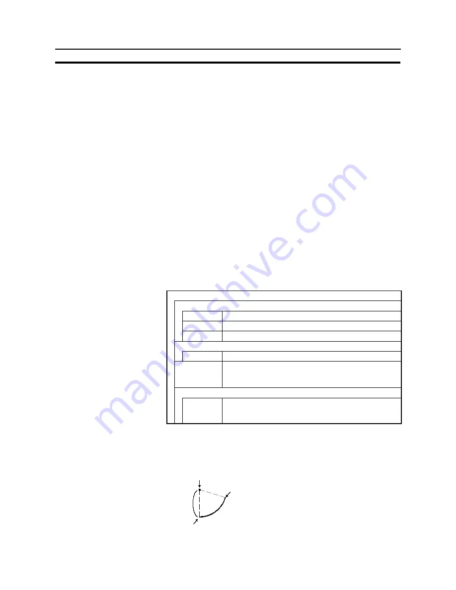
At the Support Tool, the center point, start point and end point are specified, as
shown in the figure below. When the start point is set, the radius is automati-
cally set accordingly.
Start point
Center point
End point
Radius
Содержание NT31 Series
Страница 1: ...Cat No V043 E1 2 Programmable Terminal NT31 31C OPERATION MANUAL...
Страница 2: ...iii NT31 31C Programmable Terminal Operation Manual Produced March 1999...
Страница 41: ...30 Before Operating Section 1 5...
Страница 75: ...64 Using a Memory Unit NT31 NT31C without V1 Section 3 6...
Страница 160: ...149...
Страница 174: ...163...
Страница 193: ...182...
Страница 211: ...200...
Страница 235: ...224 c Return to the screen on which screens are specified...
Страница 262: ...251...
Страница 284: ...273 The printer type control protocol and printing method are set with the memory switches of the NT31 NT31C...
Страница 347: ...336 Screen number 5 is set for touch switch 1 To next screen When touch switch 1 is pressed Screen number 5...
Страница 360: ...349 It is not possible to control a gloval window by touch switch operation...
Страница 375: ...364 For details on the method of display depending on the General settings refer to Common Attributes page 358...
Страница 391: ...380 1 The 100 value 0 value and 100 value must comply with the following relationship 100 value 0 value 100 value...
Страница 468: ...457 254 255 0 2 7 1 4 5 3 3 0 0 0 5 9 8 0 3...
Страница 476: ...465 Special Functions Section 7 16...
Страница 495: ...484 OFF...
Страница 610: ...599 Commands Responses Section 9 3...
Страница 630: ...619 Examples of Actual Applications of Memory Link Section 10 2...


