15
6
U
SER INTERFACE
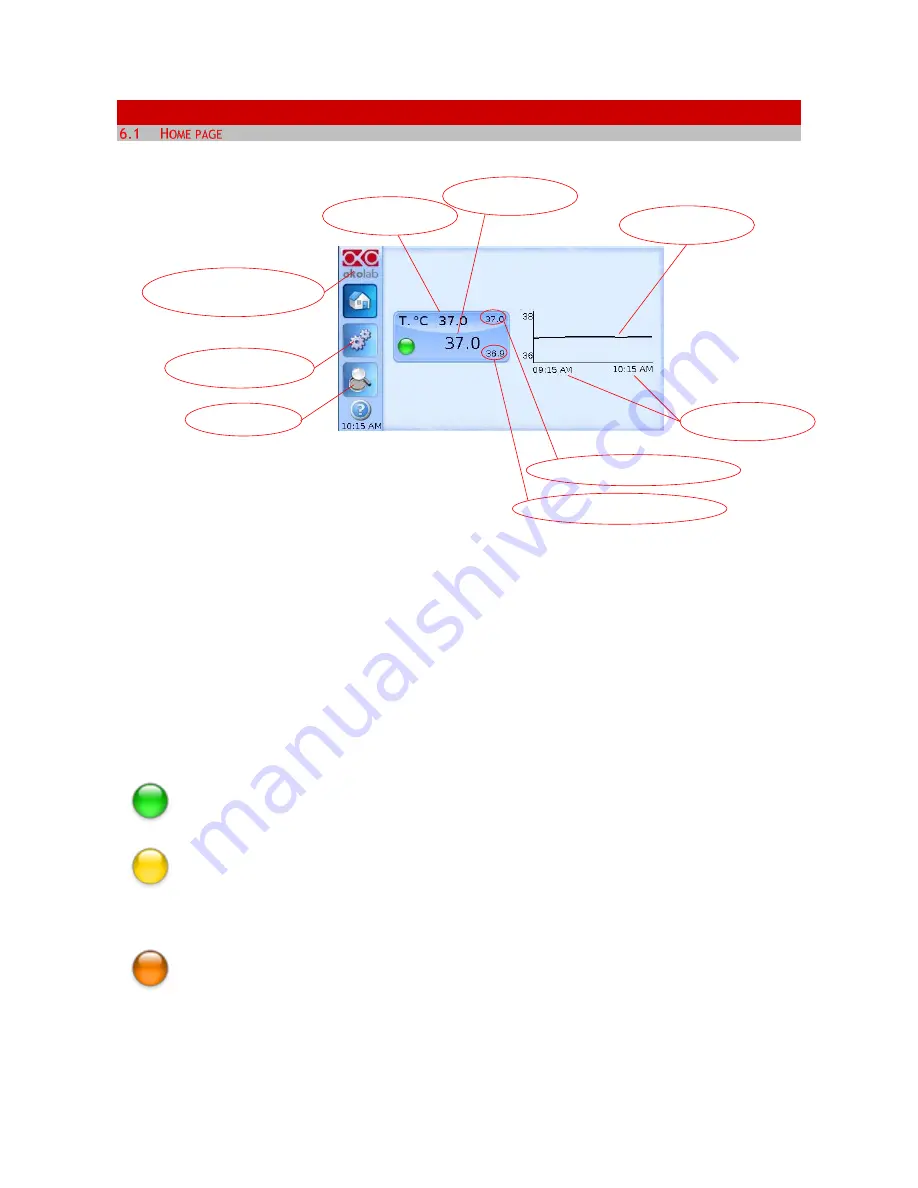
Figure 7. Homepage of the Control Unit Touch Screen Display
On the right side of the screen you will see the graph of Temperature value over time. The X axis displays
the scale of the duration of time you selected (in this example 1 hour). The Y axis, shows the temperature
scale.
Tip
►
The Touch Screen is pre-set at the following temperature: 37°C. Once turning the Touch Screen on it
will start operating to reach this set-point value.
6.1.1
Colors meaning
The
GREEN
indicator means that set-point value has been reached (within the tolerance
you’ve set) and that the system is working properly
.
The
YELLOW
indicator means that the system is working towards reaching set points. NO
actions on your part are required. The Yellow light will also appear every time you change
the Temperature set-point.
The
ORANGE
indicator means that the current gas concentration is not correct and its value
is out of the set tolerance (
see section “ALARMS”
in paragraph 6.2.2.5). While giving time to
the system to recover from this out-of-range value, please double check if there may be
reasons not depending on the unit for which it is not properly working. Verify if all cables are
correctly connected.
Maximum T °C reached within the time-period
Temperature set-point
Touch here to access system
options and settings
Touch here to go to
the OVERVIEW page
Current
Temperature value
Chart history lenght
set at 1 h
Temperature chart
Minimum T °C reached within the time-period
Touch here to know
generic info about Control
Unit and running time
Содержание H301-T-UNIT-BL-PLUS
Страница 1: ...1 H301 T UNIT BL PLUS Electric Top Stage Incubation System Manual Vers 01 17 ...
Страница 2: ...2 This page was left blank ...
Страница 33: ...33 Figure 48 Glance Mode with temperature controller CO2 O2 gas controller and active humidity controller ...
Страница 41: ...41 Contact our technical support sibillo oko lab com by e mail to take an appointment for the web assistance ...


