SECTION 3 -- FIELD OPERATION
3--133
WHEEL ADJUSTMENT
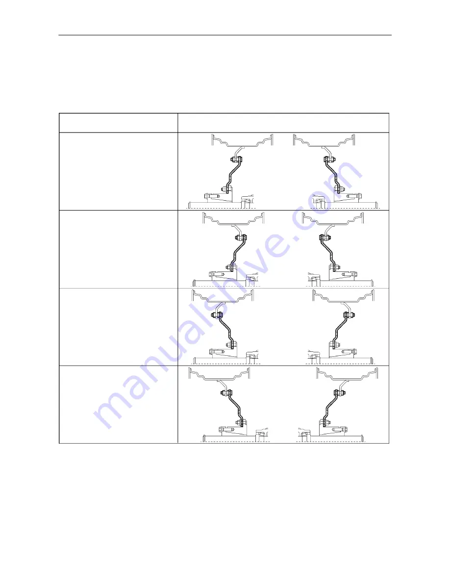
The sectioned drawings shown in Figures 229 and 230 illustrate the wheel rim and disc positions at various track
settings. In each table, two track width settings are quoted for each axle type. These are the minimum and
maximum achievable with both wheel assemblies moved fully in (toward the tractor) and fully out (away from
the tractor).
Track Adjustment
Rim and Disc Position
1524 -- 1830 mm (60 -- 72 in.)
1727 -- 2030 mm (68 -- 80 in.)
1930 -- 2235 mm (76 -- 88 in.)
2133 -- 2438 mm (84 -- 96 in.)
229
Wheels with steel centre disc bolted to flange on the rim
NOTE:
With the larger width tyres, it may not be
possible to move the wheels to the narrower settings
due to limited clearance between the tyre and fender.
NOTE:
The track widths shown in Figure 229 are
nominal and may vary from that shown dependent on
wheel and tyre size.
Содержание T6010 DELTA
Страница 1: ...OPERATOR S MANUAL T6010 T6020 T6030 T6050 T6070 Delta and Plus Tractors ...
Страница 6: ...BLANK ...
Страница 28: ...SECTION 1 GENERAL INFORMATION AND SAFETY 1 22 NOTES ...
Страница 32: ...SECTION 2 CONTROLS INSTRUMENTS AND OPERATION 2 4 PLATFORM CONTROLS 2 General View of Tractor Controls Less Cab ...
Страница 280: ...SECTION 3 FIELD OPERATION 3 146 NOTES ...
Страница 343: ...SECTION 4 LUBRICATION AND MAINTENANCE 4 63 FUSE AND RELAY LOCATIONS Fusebox Relays and Maxi Fuses 132 Relays 133 ...
Страница 366: ...SECTION 5 FAULT FINDING 5 12 NOTES ...
Страница 368: ...SECTION 6 VEHICLE STORAGE 6 2 NOTES ...
Страница 400: ...SECTION 8 SPECIFICATIONS 8 24 NOTES ...
Страница 402: ...SECTION 9 1ST 50 HOUR SERVICE SHEETS 9 2 ...
Страница 404: ...SECTION 9 1ST 50 HOUR SERVICE SHEETS 9 4 ...
Страница 410: ...SECTION 10 INDEX 10 6 ...
Страница 412: ...sblank ...


