Host Programmer Model
6
-24
DSP56303 User’s Manual
force interrupt handlers (for example, ESSI, SCI,
IRQA
,
IRQB
interrupt routines), and perform
control or debugging operations.
Note:
When the DSP enters Stop mode, the HI08 signals are electrically disconnected
internally, thus disabling the HI08 until the core leaves stop mode. While the HI08
configuration remains unchanged in Stop mode, the core cannot be restarted via the
HI08 interface. Do not issue a STOP command to the DSP via the HI08 unless you
provide some other mechanism to exit stop mode.
6.7.1
Interface Control Register (ICR)
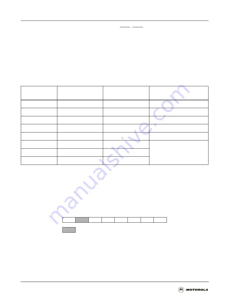
The ICR is an 8-bit read/write control register by which the host processor controls the HI08
interrupts and flags. The DSP core cannot access the ICR. The ICR is a read/write register,
which allows the use of bit manipulation instructions on control register bits. Hardware and
software reset clear the ICR bits.
Table 6-14. Host-Side Register Map
Host
Address
Big Endian
HLEND = 0
Little Endian
HLEND = 1
Register Name
0
ICR
ICR
Interface Control
1
CVR
CVR
Command Vector
2
ISR
ISR
Interface Status
3
IVR
IVR
Interrupt Vector
4
00000000
00000000
Unused
5
RXH/TXH
RXL/TXL
Receive/Transmit
Data
6
RXM/TXM
RXM/TXM
7
RXL/TXL
RXH/TXH
7
6
5
4
3
2
1
0
INIT
HLEND
HF1
HF0
HDRQ TREQ
RREQ
—Reserved bit; read as 0; write to 0 for future compatibility.
Figure 6-15. Interface Control Register (ICR)
Содержание DSP56303
Страница 1: ...DSP56303 User s Manual 24 Bit Digital Signal Processor DSP56303UM AD Revision 1 January 2001 ...
Страница 52: ...JTAG OnCE Interface 2 22 DSP56303 User s Manual ...
Страница 114: ...General Purpose Input Output GPIO 5 10 DSP56303 User s Manual ...
Страница 212: ...GPIO Signals and Registers 8 26 DSP56303 User s Manual ...
Страница 268: ...Interrupt Equates A 22 DSP56303 User s Manual ...
Страница 306: ...Programming Sheets B 38 DSP56303 User s Manual ...
Страница 320: ...Index 14 DSP56303 User s Manual ...


