Overview
6
-4
DSP56303 User’s Manual
The HI08 port can operate in multiplexed or non-multiplexed mode. In multiplexed mode
(HPCR[11]:HMUX=1), the lower eight address signals multiplex with the eight data lines. In
non-multiplexed mode (HPCR[11]:HMUX=0), the HI08 requires a chip select signal and
three address lines to select one of the eight registers accessible to the host. Eight lines are
used for data. The HI08 port can also be programmed to use a single or dual read/write data
strobe and single or double host request.
Software and hardware resets clear all DSP-side control registers and configure the HI08 as
GPIO. To select GPIO functions, clear HPCR bits 6 through 1; to select other HI08 functions,
set those same bits. If the HI08 is in GPIO mode, the HDDR configures each corresponding
signal in the HDR as an input signal if the HDDR bit is cleared or as an output signal if the
HDDR bit is set. For details, see Section 6.6.3, Host Data Direction Register (HDDR), on
page 6-16
and
Section 6.6.4, Host Data Register (HDR), on page 6-16.
6.3
Overview
The HI08 is partitioned into two register banks, as Figure 6-1 shows. The host-side register
bank is accessible only to the host, and the DSP-side register bank is accessible only to the
DSP core. For the host, the HI08 appears as eight byte-wide locations mapped in its external
address space. The DSP-side registers appear to the DSP core as six 24-bit registers mapped
into internal I/O X memory space and therefore accessible via standard DSP56300
instructions and addressing modes. In GPIO mode, two additional registers (HDDR and
HDR) are related to the HI08 peripheral.
The separate receive and transmit data paths are double buffered for efficient, high speed
asynchronous transfers. The host-side transmit data path (host writes) is also the DSP-side
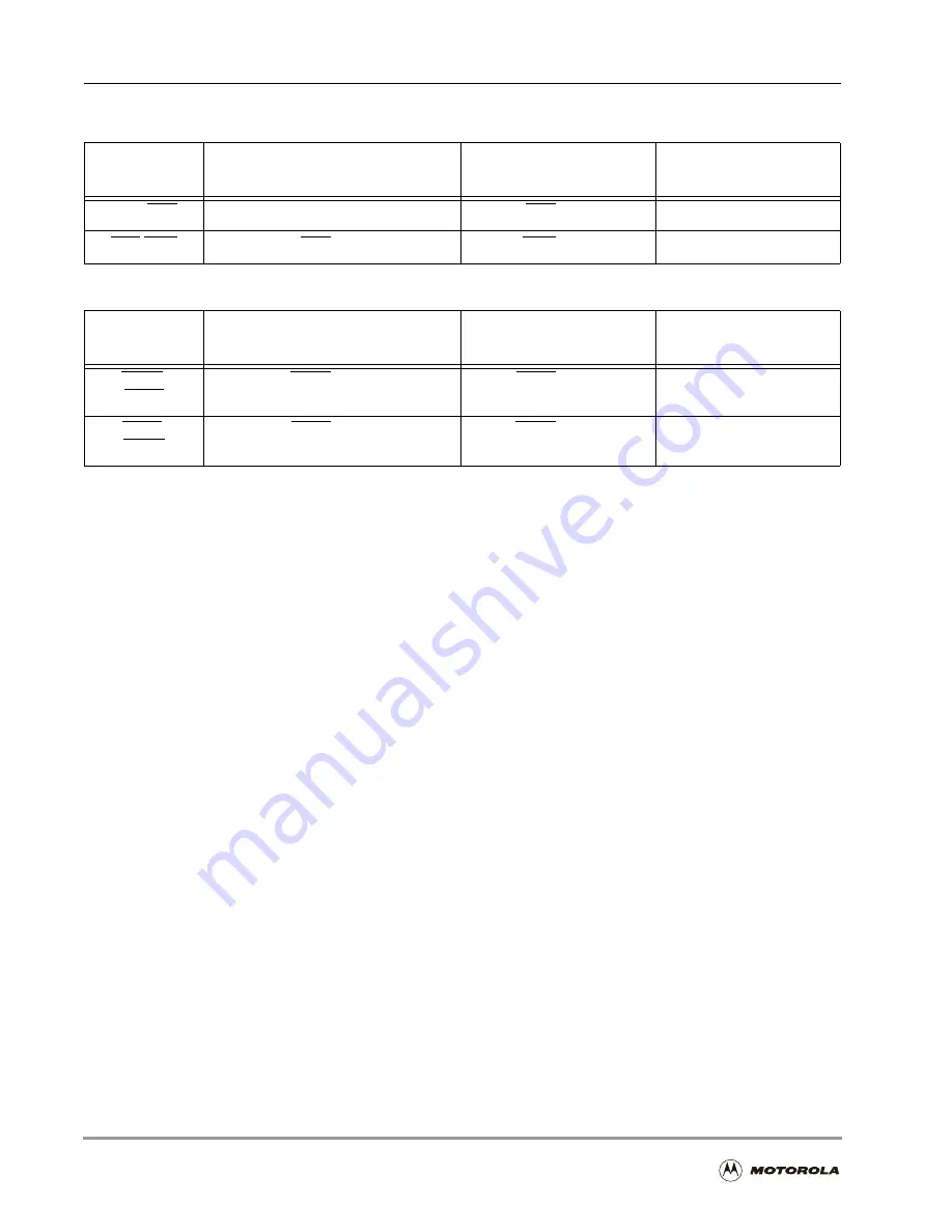
Table 6-2. HI08 Data Strobe Signals
HI08 Port
Signal
Single Strobe Mode
Dual Strobe Mode
GPIO Mode
HRW/HRD
HRW
HRD/HRD
PB11
HDS/HWR
HDS/HDS
HWR/HWR
PB12
Table 6-3. HI08 Host Request Signals
HI08 Port
Signal
Single Host Request Mode
Double Host Request
Mode
GPIO Mode
HREQ/
HTRQ
HREQ/HREQ
HTRQ/HTRQ
PB14
HACK/
HRRQ
HACK/HACK
HRRQ/HRRQ
PB15
Содержание DSP56303
Страница 1: ...DSP56303 User s Manual 24 Bit Digital Signal Processor DSP56303UM AD Revision 1 January 2001 ...
Страница 52: ...JTAG OnCE Interface 2 22 DSP56303 User s Manual ...
Страница 114: ...General Purpose Input Output GPIO 5 10 DSP56303 User s Manual ...
Страница 212: ...GPIO Signals and Registers 8 26 DSP56303 User s Manual ...
Страница 268: ...Interrupt Equates A 22 DSP56303 User s Manual ...
Страница 306: ...Programming Sheets B 38 DSP56303 User s Manual ...
Страница 320: ...Index 14 DSP56303 User s Manual ...


