Programming Model
MOTOROLA
LCD Controller
19-37
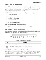
19.4.17 Mapping RAM Registers
The mapping RAM is used for mapping 4-bit codes for grayscale to the 16 gray shades, and for mapping 4-
or 8-bit color codes to either the 4096 (for active panels) or 512 colors (for passive panels). The color
RAM (0x00205800-0x00205BFC) contains 256 entries and each entry is 12 bits wide. Each RAM entry
use 4 bytes of address space. The RAM can be accessed with word transactions only and the address must
be word aligned. Unimplemented bits are read as 0. Byte or halfword access to the RAM corrupts its
contents. All read/write data use least significant twelve bits.
In 4 bpp mode, the first sixteen RAM entries are used. In 8 bpp mode, all 256 RAM entries are used. The
color RAM is not initialized at reset. With any given panel, only one of the following settings is valid:
•
1 bpp monochrome mode
•
4 bpp gray-scale mode
•
4 bpp passive matrix color mode
•
8 bpp passive matrix color mode
•
4 bpp active matrix color mode
•
8 bpp active matrix color mode
•
12/16 bpp active matrix color mode
19.4.17.1 One Bit/Pixel Monochrome Mode
The mapping RAM is not used in this mode because the LCDC uses the display data in memory to drive
the panel directly.
19.4.17.2 Four Bits/Pixel Gray-Scale Mode
In four bits/pixel gray-scale mode, a 4-bit code represents a gray-scale level. The first 16 mapping RAM
entries must be written to define the codes for all 16 combinations.
19.4.17.3 Four Bits/Pixel Passive Matrix Color Mode
In four bits/pixel passive matrix color mode, a 4-bit code represents a 12-bit color. Because just four bits
are used to encode the color, a maximum of 16 colors can be selected out of a palette of 4096. The first 16
mapping RAM entries must be written to define the codes for the 16 available combinations.
BIT
11
10
9
8
7
6
5
4
3
2
1
0
GPM
TYPE
r
r
r
r
r
r
r
r
rw
rw
rw
rw
RESET
0
0
0
0
0
0
0
0
?
?
?
?
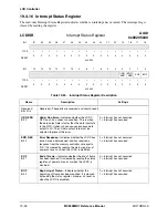
Table 19-25. Four Bits/Pixel Gray-Scale Mode
Name
Description
Reserved
Bits 11–4
Reserved—These bits are reserved and should read 0.
GPM
Bits 3–0
Gray Palette Map
—Represents the gray-scale level for a given pixel code.
Содержание DragonBall MC9328MX1
Страница 68: ...1 12 MC9328MX1 Reference Manual MOTOROLA Introduction ...
Страница 86: ...2 18 MC9328MX1 Reference Manual MOTOROLA Signal Descriptions and Pin Assignments ...
Страница 116: ...3 30 MC9328MX1 Reference Manual MOTOROLA Memory Map ...
Страница 126: ...4 10 MC9328MX1 Reference Manual MOTOROLA ARM920T Processor ...
Страница 160: ...8 8 MC9328MX1 Reference Manual MOTOROLA System Control ...
Страница 272: ...13 32 MC9328MX1 Reference Manual MOTOROLA DMA Controller ...
Страница 281: ...Programming Model MOTOROLA Watchdog Timer Module 14 9 ...
Страница 282: ...14 10 MC9328MX1 Reference Manual MOTOROLA Watchdog Timer Module ...
Страница 300: ...15 18 MC9328MX1 Reference Manual MOTOROLA Analog Signal Processor ASP ...
Страница 438: ...18 16 MC9328MX1 Reference Manual MOTOROLA Serial Peripheral Interface Modules SPI 1 and SPI 2 ...
Страница 478: ...19 40 MC9328MX1 Reference Manual MOTOROLA LCD Controller ...
Страница 542: ...20 64 MC9328MX1 Reference Manual MOTOROLA Multimedia Card Secure Digital Host Controller Module MMC SD ...
Страница 574: ...21 32 MC9328MX1 Reference Manual MOTOROLA Memory Stick Host Controller MSHC Module ...
Страница 598: ...23 16 MC9328MX1 Reference Manual MOTOROLA Real Time Clock RTC ...
Страница 670: ...24 72 MC9328MX1 Reference Manual MOTOROLA SDRAM Memory Controller ...
Страница 726: ...25 56 MC9328MX1 Reference Manual MOTOROLA SmartCard Interface Module SIM ...
Страница 736: ...26 10 MC9328MX1 Reference Manual MOTOROLA General Purpose Timers ...
Страница 854: ...29 18 MC9328MX1 Reference Manual MOTOROLA I2C Module ...
Страница 900: ...30 46 MC9328MX1 Reference Manual MOTOROLA Synchronous Serial Interface SSI ...
Страница 942: ...32 26 MC9328MX1 Reference Manual MOTOROLA GPIO Module and I O Multiplexer IOMUX ...


