25-50
MC9328MX1 Reference Manual
MOTOROLA
SmartCard Interface Module (SIM)
It is possible to disable the detection of NACKs from the SmartCard by setting XTH to 0x0. By setting
XTH to 0x1, it is possible to disable all retransmissions while still setting XTE on the first NACK
received. In general, XTE is set on the NACK that causes the threshold set by XTH to be reached. This
final NACK does not cause a retransmission, although all previous NACKs do cause a retransmission.
Section 25.2.2, “SIM Transmitter,” on page 25-2 summarizes the effect that XTH has on the operation of
the SIM transmitter.
25.9.3 Transmit Guard Time
The time between data bytes sent from the SIM transmitter can be altered through the transmit guard time
control. By default, the minimum time between start bits of successive transmitted bytes is 12 ETUs. An
ETU is equivalent to 1 bit time. Therefore, the amount of time an ETU consumes is determined by the
baud rate chosen. The 12 ETUs that form the default character transmission time consist of a start bit, 8
data bits, a parity bit and two stop bits (see Figure 25-4 on page 25-8). The number of stop bits (idle bits)
can be extended by an integer number of ETUs. The number of additional ETUs can be programmed
directly into the GETU bits of the GUARD_CNTL register (see page 25-36). Programming the GETU bits
to 0xFF configures the SIM transmitter to use only one stop bit for each character transmission.
25.9.4 Using the SIM Transmit with T = 1 SmartCards
The SIM provides hardware support for T = 1 type SmartCards. These type of cards present several
requirements above and beyond the standard T = 0 cards. The features provided to meet the requirements
that pertain to the SIM transmitter are as follows:
•
11 ETU Characters
— The SIM transmitter has a programmable guard time register that allows the programmer to
specify the number of ETUs between character transmissions. Programming a value of 255
(0xFF) in the GETU bits in the GUARD_CNTL register sets the number of ETUs per character
transmitted to 11.
•
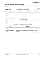
Character Waiting Time
— The character waiting time (CWT) is defined as the time between the start bits of two
consecutive characters. The value of CWT can range from 12 ETUs to 32779 ETUs. The time
between transmitted characters is controlled by the programmable guard time in the
GUARD_CNTL register. However, the time between the last byte in the transmit FIFO, and the
next transmitted byte can be largely affected by software response time to the transmit
interrupts. The SIM transmitter provides a TDTF interrupt to signal the system when the
expected number of characters have been transmitted from the transmit FIFO. The minimum
CWT is achieved only when the software can respond to the TDTF interrupt and write new data
to the transmit FIFO before the last character in the Transmit FIFO has been sent.
•
Block Waiting Time
— The block waiting time (BWT) is defined as the time between the start bits of the last character
of a received block and the first character of the next received block. The value of BWT is
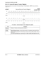
always greater than 1800 ETUs. The SIM transmitter provides a general purpose counter that
can track the BWT. The BWT is purely determined by software response time to the transmit
interrupts.
•
Block Guard Time
— The block guard time (BGT) is defined as the minimum delay between the leading edges of two
consecutive characters sent in opposite directions. The value of BGT is 22 ETUs. The SIM
supports the BGT by providing the ability to generate an interrupt when the last byte is received,
and transmitting within 2 ETUs after the XMT_EN bit in the ENABLE register is set. The BGT
Содержание DragonBall MC9328MX1
Страница 68: ...1 12 MC9328MX1 Reference Manual MOTOROLA Introduction ...
Страница 86: ...2 18 MC9328MX1 Reference Manual MOTOROLA Signal Descriptions and Pin Assignments ...
Страница 116: ...3 30 MC9328MX1 Reference Manual MOTOROLA Memory Map ...
Страница 126: ...4 10 MC9328MX1 Reference Manual MOTOROLA ARM920T Processor ...
Страница 160: ...8 8 MC9328MX1 Reference Manual MOTOROLA System Control ...
Страница 272: ...13 32 MC9328MX1 Reference Manual MOTOROLA DMA Controller ...
Страница 281: ...Programming Model MOTOROLA Watchdog Timer Module 14 9 ...
Страница 282: ...14 10 MC9328MX1 Reference Manual MOTOROLA Watchdog Timer Module ...
Страница 300: ...15 18 MC9328MX1 Reference Manual MOTOROLA Analog Signal Processor ASP ...
Страница 438: ...18 16 MC9328MX1 Reference Manual MOTOROLA Serial Peripheral Interface Modules SPI 1 and SPI 2 ...
Страница 478: ...19 40 MC9328MX1 Reference Manual MOTOROLA LCD Controller ...
Страница 542: ...20 64 MC9328MX1 Reference Manual MOTOROLA Multimedia Card Secure Digital Host Controller Module MMC SD ...
Страница 574: ...21 32 MC9328MX1 Reference Manual MOTOROLA Memory Stick Host Controller MSHC Module ...
Страница 598: ...23 16 MC9328MX1 Reference Manual MOTOROLA Real Time Clock RTC ...
Страница 670: ...24 72 MC9328MX1 Reference Manual MOTOROLA SDRAM Memory Controller ...
Страница 726: ...25 56 MC9328MX1 Reference Manual MOTOROLA SmartCard Interface Module SIM ...
Страница 736: ...26 10 MC9328MX1 Reference Manual MOTOROLA General Purpose Timers ...
Страница 854: ...29 18 MC9328MX1 Reference Manual MOTOROLA I2C Module ...
Страница 900: ...30 46 MC9328MX1 Reference Manual MOTOROLA Synchronous Serial Interface SSI ...
Страница 942: ...32 26 MC9328MX1 Reference Manual MOTOROLA GPIO Module and I O Multiplexer IOMUX ...


