32-12
MC9328MX1 Reference Manual
MOTOROLA
GPIO Module and I/O Multiplexer (IOMUX)
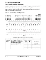
32.5.3 Input Configuration Registers
The input configuration registers ICONFA1 and ICONFA2 specify the signal or value driven to the AOUT
bus. The input configuration registers ICONFB1 and ICONFB2 specify the signal or value driven to the
BOUT bus. There are two bits in the input configuration registers for each port pin.
There are four distinct input configuration registers for each port; each holds the data for one of the four
GPIO ports (Port A, Port B, Port C, and Port D).
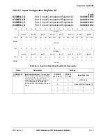
32.5.3.1 Input Configuration Register A1
ICONFA1_A
ICONFA1_B
ICONFA1_C
ICONFA1_D
Port A Input Configuration Register A1
Port B Input Configuration Register A1
Port C Input Configuration Register A1
Port D Input Configuration Register A1
Addr
0x0021C00C
0x0021C10C
0x0021C20C
0x0021C30C
BIT
31
30
29
28
27
26
25
24
23
22
21
20
19
18
17
16
ICONFA1
pin 15
pin 14
pin 13
pin 12
pin 11
pin 10
pin 9
pin 8
TYPE
rw
rw
rw
rw
rw
rw
rw
rw
rw
rw
rw
rw
rw
rw
rw
rw
RESET
1
1
1
1
1
1
1
1
1
1
1
1
1
1
1
1
0xFFFF
BIT
15
14
13
12
11
10
9
8
7
6
5
4
3
2
1
0
ICONFA1
pin 7
pin 6
pin 5
pin 4
pin 3
pin 2
pin 1
pin 0
TYPE
rw
rw
rw
rw
rw
rw
rw
rw
rw
rw
rw
rw
rw
rw
rw
rw
RESET
1
1
1
1
1
1
1
1
1
1
1
1
1
1
1
1
0xFFFF
Table 32-8. Input Configuration Register A1 Description
Name
Description
Settings
ICONFA1 [i]
Bits 31
–
0
Input Configuration
—Corresponds to
pins 0–15 of the port and defines which
one of the four options is driven to
AOUT [i]. Each port pin [i] (i = 0 through
15) requires two ICONFA1 bits to
determine the input value.
ICONFA1
[2i + 1]
ICONFA1
[2i]
Input Selected
0
0
GPIO-In [i]
0
1
Interrupt Status Register [i]
1
0
0
1
1
1
Содержание DragonBall MC9328MX1
Страница 68: ...1 12 MC9328MX1 Reference Manual MOTOROLA Introduction ...
Страница 86: ...2 18 MC9328MX1 Reference Manual MOTOROLA Signal Descriptions and Pin Assignments ...
Страница 116: ...3 30 MC9328MX1 Reference Manual MOTOROLA Memory Map ...
Страница 126: ...4 10 MC9328MX1 Reference Manual MOTOROLA ARM920T Processor ...
Страница 160: ...8 8 MC9328MX1 Reference Manual MOTOROLA System Control ...
Страница 272: ...13 32 MC9328MX1 Reference Manual MOTOROLA DMA Controller ...
Страница 281: ...Programming Model MOTOROLA Watchdog Timer Module 14 9 ...
Страница 282: ...14 10 MC9328MX1 Reference Manual MOTOROLA Watchdog Timer Module ...
Страница 300: ...15 18 MC9328MX1 Reference Manual MOTOROLA Analog Signal Processor ASP ...
Страница 438: ...18 16 MC9328MX1 Reference Manual MOTOROLA Serial Peripheral Interface Modules SPI 1 and SPI 2 ...
Страница 478: ...19 40 MC9328MX1 Reference Manual MOTOROLA LCD Controller ...
Страница 542: ...20 64 MC9328MX1 Reference Manual MOTOROLA Multimedia Card Secure Digital Host Controller Module MMC SD ...
Страница 574: ...21 32 MC9328MX1 Reference Manual MOTOROLA Memory Stick Host Controller MSHC Module ...
Страница 598: ...23 16 MC9328MX1 Reference Manual MOTOROLA Real Time Clock RTC ...
Страница 670: ...24 72 MC9328MX1 Reference Manual MOTOROLA SDRAM Memory Controller ...
Страница 726: ...25 56 MC9328MX1 Reference Manual MOTOROLA SmartCard Interface Module SIM ...
Страница 736: ...26 10 MC9328MX1 Reference Manual MOTOROLA General Purpose Timers ...
Страница 854: ...29 18 MC9328MX1 Reference Manual MOTOROLA I2C Module ...
Страница 900: ...30 46 MC9328MX1 Reference Manual MOTOROLA Synchronous Serial Interface SSI ...
Страница 942: ...32 26 MC9328MX1 Reference Manual MOTOROLA GPIO Module and I O Multiplexer IOMUX ...

