16-14
MC9328MX1 Reference Manual
MOTOROLA
Bluetooth Accelerator (BTA)
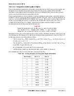
16.3.1.8.1 Frequency Synthesizer and Timing Control
Data is written to the RF front ends through the SPI_WORD0, SPI_WORD1, SPI_WORD2,
SPI_WORD3,
SPI_READ_ADDR and SPI_WRITE_ADDR
registers. These registers are primarily used to
program the frequency synthesizer of the RF front-end. Depending on the RF front end used, only some of
the six interface registers are required.
In addition to the data interface, the Bluetooth core includes two registers, TIME_A_B and TIME_C_D,
that are used to specify the timing of control signals to the RF module. The time written to the these
registers refer to the number of µs before SysTick.
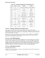
16.3.1.8.2 Pulse Width Modulators
RF control includes two pulse width modulators (PWMs) used to control transmit power and to generate
the Received Signal Strength Indicator (RSSI). Both PWMs are clocked by the 8 MHz clock providing a
resolution of 125 ns. They share the same 6-bit PWM counter. The transmit PWM and RSSI PWM are
enabled by the PWM_TX_EN and RSSI_EN bits in the RF_CONTROL register respectively. When enabled,
the PWM provides a pulse resolution of 32 steps and cycle time of 8 µs. The desired transmit power is
written to the PWM_TX register while the RSSI value is written to the PWM_RSSI register.
16.3.1.8.3 Radio Module Interfaces
MC13180 Radio (3 Wire SPI)
The MC13180 radio is programmed via a three wire serial programming interface (SPI) comprised of the
spi_data, spi_en, and spi_clk lines.
Table 16-8. Bluetooth Pin Mapping for Various Radio Interfaces
Name
Direction
Reset
MC13180
SiW1502
BT1
IN
—
Ref_Clk (In: 24 MHz)
Ref_Clk (In: 16 MHz)
BT2
Tri-State Out
Hi-Z
Tx_Data
TxData
BT3
In
—
Rx_Data
RxData
BT4
In
—
spi_data_in
SPI_TXD
BT5
In/Out
In
In: Frame_Synch
Out: PWM_RSSI
BT6
Out
Low
PWM_Tx/GPO1
Reset_RM
BT7
Out
Low
Diversity/BTRFOSC
Diversity/Enable_RM
BT8
Tri-State Out
Hi-Z
PWM_RSSI
TxEN
BT9
Out
Low
RxTx_en
HOP_STRB
BT10
Out
High
BTRFOSC/GPO2
BTRFOSC/GPO2
BT11
Out
High
spi_en
SPI_SS
BT12
Tri-State Out
Hi-Z
spi_data_out
SPI_RXD
BT13
Out
Low
spi_clk
SPI_CLK
Содержание DragonBall MC9328MX1
Страница 68: ...1 12 MC9328MX1 Reference Manual MOTOROLA Introduction ...
Страница 86: ...2 18 MC9328MX1 Reference Manual MOTOROLA Signal Descriptions and Pin Assignments ...
Страница 116: ...3 30 MC9328MX1 Reference Manual MOTOROLA Memory Map ...
Страница 126: ...4 10 MC9328MX1 Reference Manual MOTOROLA ARM920T Processor ...
Страница 160: ...8 8 MC9328MX1 Reference Manual MOTOROLA System Control ...
Страница 272: ...13 32 MC9328MX1 Reference Manual MOTOROLA DMA Controller ...
Страница 281: ...Programming Model MOTOROLA Watchdog Timer Module 14 9 ...
Страница 282: ...14 10 MC9328MX1 Reference Manual MOTOROLA Watchdog Timer Module ...
Страница 300: ...15 18 MC9328MX1 Reference Manual MOTOROLA Analog Signal Processor ASP ...
Страница 438: ...18 16 MC9328MX1 Reference Manual MOTOROLA Serial Peripheral Interface Modules SPI 1 and SPI 2 ...
Страница 478: ...19 40 MC9328MX1 Reference Manual MOTOROLA LCD Controller ...
Страница 542: ...20 64 MC9328MX1 Reference Manual MOTOROLA Multimedia Card Secure Digital Host Controller Module MMC SD ...
Страница 574: ...21 32 MC9328MX1 Reference Manual MOTOROLA Memory Stick Host Controller MSHC Module ...
Страница 598: ...23 16 MC9328MX1 Reference Manual MOTOROLA Real Time Clock RTC ...
Страница 670: ...24 72 MC9328MX1 Reference Manual MOTOROLA SDRAM Memory Controller ...
Страница 726: ...25 56 MC9328MX1 Reference Manual MOTOROLA SmartCard Interface Module SIM ...
Страница 736: ...26 10 MC9328MX1 Reference Manual MOTOROLA General Purpose Timers ...
Страница 854: ...29 18 MC9328MX1 Reference Manual MOTOROLA I2C Module ...
Страница 900: ...30 46 MC9328MX1 Reference Manual MOTOROLA Synchronous Serial Interface SSI ...
Страница 942: ...32 26 MC9328MX1 Reference Manual MOTOROLA GPIO Module and I O Multiplexer IOMUX ...


