Programming Model
MOTOROLA
Interrupt Controller (AITC)
10-9
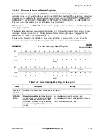
10.4.2 Normal Interrupt Mask Register
The Normal Interrupt Mask Register (NIMASK) controls the normal interrupt mask level. All normal
interrupts with a priority level less than or equal to the NIMASK are disabled. The priority levels of normal
interrupts are determined by the normal interrupt priority level registers (NIPRIORITY7, NIPRIORITY6,
NIPRIORITY5, NIPRIORITY4, NIPRIORITY3, NIPRIORITY2, NIPRIORITY1, and NIPRIORITY0).
The reset state of this register does not disable any normal interrupts.
Writing all 1’s, or
–
1, to the NIMASK sets the normal interrupt mask to
–
1 and does not disable any normal
interrupt priority levels.
This hardware mechanism creates reentrant normal interrupt routines by disabling lower priority normal
interrupts. Refer to Section 10.5.6, “Writing Reentrant Normal Interrupt Routines,” on page 10-36 for
more details on the use of the NIMASK register.
This register is located on the ARM920T processor’s native bus, is accessible in 1 cycle, and can be
accessed only in supervisor mode. This register must be accessed only on word (32-bit) boundaries.
NIMASK
Normal Interrupt Mask Register
Addr
0x00223004
BIT
31
30
29
28
27
26
25
24
23
22
21
20
19
18
17
16
TYPE
r
r
r
r
r
r
r
r
r
r
r
r
r
r
r
r
RESET
0
0
0
0
0
0
0
0
0
0
0
0
0
0
0
0
0x0000
BIT
15
14
13
12
11
10
9
8
7
6
5
4
3
2
1
0
NIMASK
TYPE
r
r
r
r
r
r
r
r
r
r
r
rw
rw
rw
rw
rw
RESET
0
0
0
0
0
0
0
0
0
0
0
1
1
1
1
1
0x001F
Table 10-5. Normal Interrupt Mask Register Description
Name
Description
Settings
Reserved
Bits 31–5
Reserved—These bits are reserved and should read 0.
NIMASK
Bits 4–0
Normal Interrupt Mask
—Controls normal
interrupt mask level. All normal interrupts
of priority level less than or equal to the
NIMASK are disabled. Settings are shown
in decimal. Setting bit 4 disables all normal
interrupts.
0 = Disable priority level 0 normal interrupts
1 = Disable priority level 1 and lower normal interrupts
...
16+ = Disable all normal interrupts.
Содержание DragonBall MC9328MX1
Страница 68: ...1 12 MC9328MX1 Reference Manual MOTOROLA Introduction ...
Страница 86: ...2 18 MC9328MX1 Reference Manual MOTOROLA Signal Descriptions and Pin Assignments ...
Страница 116: ...3 30 MC9328MX1 Reference Manual MOTOROLA Memory Map ...
Страница 126: ...4 10 MC9328MX1 Reference Manual MOTOROLA ARM920T Processor ...
Страница 160: ...8 8 MC9328MX1 Reference Manual MOTOROLA System Control ...
Страница 272: ...13 32 MC9328MX1 Reference Manual MOTOROLA DMA Controller ...
Страница 281: ...Programming Model MOTOROLA Watchdog Timer Module 14 9 ...
Страница 282: ...14 10 MC9328MX1 Reference Manual MOTOROLA Watchdog Timer Module ...
Страница 300: ...15 18 MC9328MX1 Reference Manual MOTOROLA Analog Signal Processor ASP ...
Страница 438: ...18 16 MC9328MX1 Reference Manual MOTOROLA Serial Peripheral Interface Modules SPI 1 and SPI 2 ...
Страница 478: ...19 40 MC9328MX1 Reference Manual MOTOROLA LCD Controller ...
Страница 542: ...20 64 MC9328MX1 Reference Manual MOTOROLA Multimedia Card Secure Digital Host Controller Module MMC SD ...
Страница 574: ...21 32 MC9328MX1 Reference Manual MOTOROLA Memory Stick Host Controller MSHC Module ...
Страница 598: ...23 16 MC9328MX1 Reference Manual MOTOROLA Real Time Clock RTC ...
Страница 670: ...24 72 MC9328MX1 Reference Manual MOTOROLA SDRAM Memory Controller ...
Страница 726: ...25 56 MC9328MX1 Reference Manual MOTOROLA SmartCard Interface Module SIM ...
Страница 736: ...26 10 MC9328MX1 Reference Manual MOTOROLA General Purpose Timers ...
Страница 854: ...29 18 MC9328MX1 Reference Manual MOTOROLA I2C Module ...
Страница 900: ...30 46 MC9328MX1 Reference Manual MOTOROLA Synchronous Serial Interface SSI ...
Страница 942: ...32 26 MC9328MX1 Reference Manual MOTOROLA GPIO Module and I O Multiplexer IOMUX ...


