Memory Stick Command Register
MOTOROLA
Memory Stick Host Controller (MSHC) Module
21-21
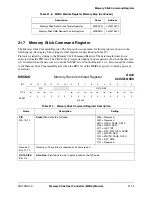
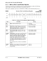
21.7.7 Memory Stick Auto Command Register
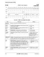
The Memory Stick Auto Command Register is a 16-bit register. The bit position assignments for this
register are shown in the following register display. The settings for this register are described in
Table 21.7.7.
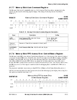
21.7.8 Memory Stick FIFO Access Error Control/Status Register
The Memory Stick FIFO Access Error Control/Status Register is a 16-bit register. This register’s purpose
is to detect an invalid FIFO access from Host bus side. For example, when Rx FIFO is empty, when Host
or DMAC reads the FIFO, the access means that underrun operation is caused. When Tx FIFO is full,
when Host or DMAC writes the FIFO, the access means that overrun operation is caused. However,
because the FIFO’s pointer does not advance in spite of these invalid accesses, user does not need to clear
the FIFO in such cases. This register would be useful for debugging Host’s and DMAC’s FIFO access
operation.
This register is initialized on power up or when RST bit of Memory Stick Control/Status Register is 1.
The bit position assignments for this register are shown in the following register display. The settings for
this register are described in Table 21-15.
MSACD
Memory Stick Auto Command Register
Addr
0x0021A00C
BIT
15
14
13
12
11
10
9
8
7
6
5
4
3
2
1
0
APID
ADATASIZE
TYPE
rw
rw
rw
rw
r
r
rw
rw
rw
rw
rw
rw
rw
rw
rw
rw
RESET
0
1
1
1
0
0
0
0
0
0
0
0
0
0
0
1
0x7001
Table 21-14. Memory Stick Auto Command Register Description
Name
Description
Setting
APID
Bits 15–12
Auto Command PID
—Sets the PID to be
automatically executed.
0100 = READ_REG
0111 = GET_INT
All Others Reserved
Reserved
Bits 11–10
Reserved—These bits are reserved and should read 0.
ADATASIZE
Bits 9–0
Auto Command Data Size
—Sets the data size in bytes.
MSFAECS
Memory Stick FIFO Access Error
Control/Status Register
Addr
0x0021A00E
BIT
15
14
13
12
11
10
9
8
7
6
5
4
3
2
1
0
FAEEN
RUN
TOV
TYPE
r
r
r
r
r
r
r
rw
r
r
r
r
r
r
rw
rw
RESET
0
0
0
0
0
0
0
0
0
0
0
0
0
0
0
0
0x0000
Содержание DragonBall MC9328MX1
Страница 68: ...1 12 MC9328MX1 Reference Manual MOTOROLA Introduction ...
Страница 86: ...2 18 MC9328MX1 Reference Manual MOTOROLA Signal Descriptions and Pin Assignments ...
Страница 116: ...3 30 MC9328MX1 Reference Manual MOTOROLA Memory Map ...
Страница 126: ...4 10 MC9328MX1 Reference Manual MOTOROLA ARM920T Processor ...
Страница 160: ...8 8 MC9328MX1 Reference Manual MOTOROLA System Control ...
Страница 272: ...13 32 MC9328MX1 Reference Manual MOTOROLA DMA Controller ...
Страница 281: ...Programming Model MOTOROLA Watchdog Timer Module 14 9 ...
Страница 282: ...14 10 MC9328MX1 Reference Manual MOTOROLA Watchdog Timer Module ...
Страница 300: ...15 18 MC9328MX1 Reference Manual MOTOROLA Analog Signal Processor ASP ...
Страница 438: ...18 16 MC9328MX1 Reference Manual MOTOROLA Serial Peripheral Interface Modules SPI 1 and SPI 2 ...
Страница 478: ...19 40 MC9328MX1 Reference Manual MOTOROLA LCD Controller ...
Страница 542: ...20 64 MC9328MX1 Reference Manual MOTOROLA Multimedia Card Secure Digital Host Controller Module MMC SD ...
Страница 574: ...21 32 MC9328MX1 Reference Manual MOTOROLA Memory Stick Host Controller MSHC Module ...
Страница 598: ...23 16 MC9328MX1 Reference Manual MOTOROLA Real Time Clock RTC ...
Страница 670: ...24 72 MC9328MX1 Reference Manual MOTOROLA SDRAM Memory Controller ...
Страница 726: ...25 56 MC9328MX1 Reference Manual MOTOROLA SmartCard Interface Module SIM ...
Страница 736: ...26 10 MC9328MX1 Reference Manual MOTOROLA General Purpose Timers ...
Страница 854: ...29 18 MC9328MX1 Reference Manual MOTOROLA I2C Module ...
Страница 900: ...30 46 MC9328MX1 Reference Manual MOTOROLA Synchronous Serial Interface SSI ...
Страница 942: ...32 26 MC9328MX1 Reference Manual MOTOROLA GPIO Module and I O Multiplexer IOMUX ...


