24-18
MC9328MX1 Reference Manual
MOTOROLA
SDRAM Memory Controller
24.6 Operating Modes
Each of the SDRAM Controller operating modes is described in this section, including details on basic
operation, relationship to SDRAM/SyncFlash operating modes, and any special precautions to observe.
State and timing diagrams are included where appropriate.
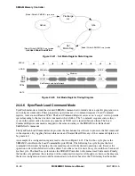
24.6.1 SDRAM and SyncFlash Command Encoding
Table 24-11 summarizes the command encodings used by the SDRAM controller. This command list is a
subset of the commands defined by the JEDEC standard. Note that the SDRAM Auto, Self-Refresh, and
SyncFlash Load Command register commands share the same encoding. Also note, that encodings are
based from the view of the SDRAM memory to the controller, and therefore use SDRAM signal names.
See Figure 24-46 on page 24-50 for an example.
Assertion of the sd_rst signal initializes the controller into the idle state. As long as the SDRAM Controller
is not the boot source, that assertion also disables the module. While disabled, the controller remains in the
idle state with the internal clocks stopped.
If the SDRAM Controller has been selected as the boot device, then the module is enabled following reset.
The reset state of the control register allows for basic read/write operations sufficient to fetch the reset
vector and execute the initialization code. A complete initialization of the controller must be performed as
part of the start-up code sequence.
Table 24-11. SDRAM and SyncFlash Command Encoding
Function
Symbol
CKE
n-1
CKE
n
CS
RAS
CAS
WE
A11
A10
BA
[1:0]
A
[9:0]
Deselect
DSEL
H
X
H
X
X
X
X
X
X
X
No operation
NOP
H
X
L
H
H
H
X
X
X
X
Read
READ
H
X
L
H
L
H
V
L
V
V
Write
WRIT
H
X
L
H
L
L
V
L
V
V
Bank activate
ACT
H
X
L
L
H
H
V
V
V
V
Burst terminate
TBST
H
X
L
H
H
L
X
X
V
X
Precharge select bank
PRE
H
X
L
L
H
L
V
L
X
X
Precharge all banks
PALL
H
X
L
L
H
L
X
H
X
X
Auto-refresh
CBR
H
X
L
L
L
H
X
X
X
X
SyncFlash load
command register
LCR
H
X
L
L
L
H
X
X
V
V
Self refresh entry
SLFRSH
H
L
L
L
L
H
X
X
X
X
Self refresh exit
SLFRSHX
L
H
H
X
X
X
X
X
X
X
Power-down entry
PWRDN
H
L
X
X
X
X
X
X
X
X
Power-down exit
PWRDNX
L
H
H
X
X
X
X
X
X
X
Mode register set
MRS
H
X
L
L
L
L
L
L
V
V
Содержание DragonBall MC9328MX1
Страница 68: ...1 12 MC9328MX1 Reference Manual MOTOROLA Introduction ...
Страница 86: ...2 18 MC9328MX1 Reference Manual MOTOROLA Signal Descriptions and Pin Assignments ...
Страница 116: ...3 30 MC9328MX1 Reference Manual MOTOROLA Memory Map ...
Страница 126: ...4 10 MC9328MX1 Reference Manual MOTOROLA ARM920T Processor ...
Страница 160: ...8 8 MC9328MX1 Reference Manual MOTOROLA System Control ...
Страница 272: ...13 32 MC9328MX1 Reference Manual MOTOROLA DMA Controller ...
Страница 281: ...Programming Model MOTOROLA Watchdog Timer Module 14 9 ...
Страница 282: ...14 10 MC9328MX1 Reference Manual MOTOROLA Watchdog Timer Module ...
Страница 300: ...15 18 MC9328MX1 Reference Manual MOTOROLA Analog Signal Processor ASP ...
Страница 438: ...18 16 MC9328MX1 Reference Manual MOTOROLA Serial Peripheral Interface Modules SPI 1 and SPI 2 ...
Страница 478: ...19 40 MC9328MX1 Reference Manual MOTOROLA LCD Controller ...
Страница 542: ...20 64 MC9328MX1 Reference Manual MOTOROLA Multimedia Card Secure Digital Host Controller Module MMC SD ...
Страница 574: ...21 32 MC9328MX1 Reference Manual MOTOROLA Memory Stick Host Controller MSHC Module ...
Страница 598: ...23 16 MC9328MX1 Reference Manual MOTOROLA Real Time Clock RTC ...
Страница 670: ...24 72 MC9328MX1 Reference Manual MOTOROLA SDRAM Memory Controller ...
Страница 726: ...25 56 MC9328MX1 Reference Manual MOTOROLA SmartCard Interface Module SIM ...
Страница 736: ...26 10 MC9328MX1 Reference Manual MOTOROLA General Purpose Timers ...
Страница 854: ...29 18 MC9328MX1 Reference Manual MOTOROLA I2C Module ...
Страница 900: ...30 46 MC9328MX1 Reference Manual MOTOROLA Synchronous Serial Interface SSI ...
Страница 942: ...32 26 MC9328MX1 Reference Manual MOTOROLA GPIO Module and I O Multiplexer IOMUX ...


