Programming Model
MOTOROLA
LCD Controller
19-25
19.4.6 Vertical Configuration Register
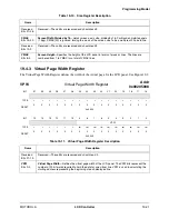
The Vertical Configuration Register defines the vertical sync pulse timing.
VCR
Vertical Configuration Register
Addr
0x00205020
BIT
31
30
29
28
27
26
25
24
23
22
21
20
19
18
17
16
V_WIDTH
TYPE
rw
rw
rw
rw
rw
rw
r
r
rw
rw
rw
rw
rw
rw
rw
rw
RESET
0
0
0
0
0
1
0
0
0
0
0
0
0
0
0
1
0x0401
BIT
15
14
13
12
11
10
9
8
7
6
5
4
3
2
1
0
V_WAIT_1
V_WAIT_2
TYPE
rw
rw
rw
rw
rw
rw
rw
rw
rw
rw
rw
rw
rw
rw
rw
rw
RESET
0
0
0
0
0
0
0
0
0
0
0
0
0
0
0
0
0x0000
Table 19-14. Vertical Configuration Register Description
Name
Description
V_WIDTH
Bits 31–26
Vertical Sync Pulse Width
—Specifies the width, in lines, of the VSYNC pulse for active (TFT =1)
mode. For a value of “000001”, the vertical sync pulse encompasses one HSYNC pulse. For a
value of “000002”, the vertical sync pulse encompasses two HSYNC pulses, and so on. For
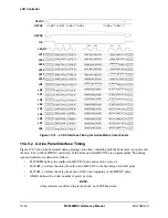
passive (TFT=0) mode and non-color mode, see Figure 19-12.
Reserved
Bits 25–16
Reserved—These bits are reserved and should read 0.
V_WAIT_1
Bits 15–8
Wait Between Frames 1
—Defines the delay, in lines, between the end of the OE pulse and the
beginning of the VSYNC pulse for active (TFT=1) mode. This field has no meaning in passive
non-color mode. The actual delay is (V_WAIT_1). In passive color mode, this field is the delay,
measured in virtual clock periods, between the last line of the frame to the beginning of the next
frame.
V_WAIT_2
Bits 7–0
Wait Between Frames 2
—Defines the delay, in lines, between the end of the VSYNC pulse and
the beginning of the OE pulse of the first line in active (TFT=1) mode. The actual delay is
V_WAIT_2 ) lines. Set this field to zero for passive non-color mode. The minimum value of this
field is 0x01.
Содержание DragonBall MC9328MX1
Страница 68: ...1 12 MC9328MX1 Reference Manual MOTOROLA Introduction ...
Страница 86: ...2 18 MC9328MX1 Reference Manual MOTOROLA Signal Descriptions and Pin Assignments ...
Страница 116: ...3 30 MC9328MX1 Reference Manual MOTOROLA Memory Map ...
Страница 126: ...4 10 MC9328MX1 Reference Manual MOTOROLA ARM920T Processor ...
Страница 160: ...8 8 MC9328MX1 Reference Manual MOTOROLA System Control ...
Страница 272: ...13 32 MC9328MX1 Reference Manual MOTOROLA DMA Controller ...
Страница 281: ...Programming Model MOTOROLA Watchdog Timer Module 14 9 ...
Страница 282: ...14 10 MC9328MX1 Reference Manual MOTOROLA Watchdog Timer Module ...
Страница 300: ...15 18 MC9328MX1 Reference Manual MOTOROLA Analog Signal Processor ASP ...
Страница 438: ...18 16 MC9328MX1 Reference Manual MOTOROLA Serial Peripheral Interface Modules SPI 1 and SPI 2 ...
Страница 478: ...19 40 MC9328MX1 Reference Manual MOTOROLA LCD Controller ...
Страница 542: ...20 64 MC9328MX1 Reference Manual MOTOROLA Multimedia Card Secure Digital Host Controller Module MMC SD ...
Страница 574: ...21 32 MC9328MX1 Reference Manual MOTOROLA Memory Stick Host Controller MSHC Module ...
Страница 598: ...23 16 MC9328MX1 Reference Manual MOTOROLA Real Time Clock RTC ...
Страница 670: ...24 72 MC9328MX1 Reference Manual MOTOROLA SDRAM Memory Controller ...
Страница 726: ...25 56 MC9328MX1 Reference Manual MOTOROLA SmartCard Interface Module SIM ...
Страница 736: ...26 10 MC9328MX1 Reference Manual MOTOROLA General Purpose Timers ...
Страница 854: ...29 18 MC9328MX1 Reference Manual MOTOROLA I2C Module ...
Страница 900: ...30 46 MC9328MX1 Reference Manual MOTOROLA Synchronous Serial Interface SSI ...
Страница 942: ...32 26 MC9328MX1 Reference Manual MOTOROLA GPIO Module and I O Multiplexer IOMUX ...

