GPIO Module Overview
MOTOROLA
GPIO Module and I/O Multiplexer (IOMUX)
32-3
32.2.2 Interrupts
The interrupt block inside the GPIO module controls all GPIO interrupt signals. Inside this block,
interrupts are defined as positive edge triggered, negative edge triggered, positive level sensitive, negative
level sensitive, or masked. For edge triggered interrupts, the edge is detected by the GPIO interrupt block
and is converted to a low level interrupt that is routed to other internal modules. When the interrupt is
masked, a value of
1
is driven to the interrupt controller regardless of the GPIO input value. The interrupts
waiting for service are stored in the Interrupt Status Register (ISR) for that port. Write a value of
1
to the
ISR to clear the interrupt. The logical OR of all the non-masked interrupt lines is available as an output
from the port. Individual interrupts for each port pin may also be output to other internal modules.
32.2.3 GPIO Signal Description
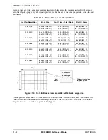
The circuitry for a single pin of the GPIO module is shown in Figure 32-2 on page 32-4. The signals shown
in that figure and the signals shown in Figure 32-1 on page 32-2 are described in Table 32-1.
Table 32-1. GPIO External Pins Description
Signal Name
Direction
Description
AIN
Input
A 32-bit input from MC9328MX1. Any signal may be connected. This input may be
reflected to GPIO output (GPIO-Out in Figure 32-2) by appropriate GPIO
configuration.
BIN
Input
Same as AIN.
CIN
Input
Same as AIN.
AOUT
Output
A 32-bit output from the GPIO that connects external pins to internal signals in the
MC9328MX1, sends an interrupt signal to an internal module, or is connected high or
low.
BOUT
Output
Same as AOUT.
GIUS_X
Output
Represents one of four GPIO In-Use Registers (GIUS). Connects to the IOMUX
module and selects whether a pin is used for GPIO or a peripheral function.
GPR_X
Output
Represents one of the four General Purpose Registers (GPR). Connects to the
IOMUX module and selects whether a pin is used for its primary or alternate function.
PUEN_X
Output
Selects whether the port pin is pulled up to a logic high.
GPIO_INT
Output
The OR value of all 32 interrupt lines. Each pin [i] of the port corresponds to pin [i] of
the ISR register.
Содержание DragonBall MC9328MX1
Страница 68: ...1 12 MC9328MX1 Reference Manual MOTOROLA Introduction ...
Страница 86: ...2 18 MC9328MX1 Reference Manual MOTOROLA Signal Descriptions and Pin Assignments ...
Страница 116: ...3 30 MC9328MX1 Reference Manual MOTOROLA Memory Map ...
Страница 126: ...4 10 MC9328MX1 Reference Manual MOTOROLA ARM920T Processor ...
Страница 160: ...8 8 MC9328MX1 Reference Manual MOTOROLA System Control ...
Страница 272: ...13 32 MC9328MX1 Reference Manual MOTOROLA DMA Controller ...
Страница 281: ...Programming Model MOTOROLA Watchdog Timer Module 14 9 ...
Страница 282: ...14 10 MC9328MX1 Reference Manual MOTOROLA Watchdog Timer Module ...
Страница 300: ...15 18 MC9328MX1 Reference Manual MOTOROLA Analog Signal Processor ASP ...
Страница 438: ...18 16 MC9328MX1 Reference Manual MOTOROLA Serial Peripheral Interface Modules SPI 1 and SPI 2 ...
Страница 478: ...19 40 MC9328MX1 Reference Manual MOTOROLA LCD Controller ...
Страница 542: ...20 64 MC9328MX1 Reference Manual MOTOROLA Multimedia Card Secure Digital Host Controller Module MMC SD ...
Страница 574: ...21 32 MC9328MX1 Reference Manual MOTOROLA Memory Stick Host Controller MSHC Module ...
Страница 598: ...23 16 MC9328MX1 Reference Manual MOTOROLA Real Time Clock RTC ...
Страница 670: ...24 72 MC9328MX1 Reference Manual MOTOROLA SDRAM Memory Controller ...
Страница 726: ...25 56 MC9328MX1 Reference Manual MOTOROLA SmartCard Interface Module SIM ...
Страница 736: ...26 10 MC9328MX1 Reference Manual MOTOROLA General Purpose Timers ...
Страница 854: ...29 18 MC9328MX1 Reference Manual MOTOROLA I2C Module ...
Страница 900: ...30 46 MC9328MX1 Reference Manual MOTOROLA Synchronous Serial Interface SSI ...
Страница 942: ...32 26 MC9328MX1 Reference Manual MOTOROLA GPIO Module and I O Multiplexer IOMUX ...


