336
9 USING FUNCTIONAL SAFETY [G] [WG]
9.3 Specifications
9.3
Specifications
For information on safety sub-function specifications, refer to "Functional safety" in the User's Manual (Introduction).
9.4
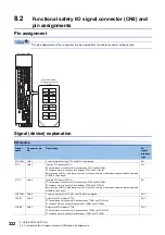
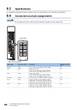
Connectors and pin assignments
The pin assignments of the connectors are as viewed from the cable connector wiring section.
• Signal device explanations
Signal name
Connector pin No.
Description
I/O signal interface
type
SDICOM
CN8-3
Common terminal for the SDIA and SDIB input signals.
DI-1
SDIA
CN8-4
Input the status of SDIA.
Turning off SDIA: Open between SDIA and SDICOM.
Turning on SDIA: Close between SDIA and SDICOM.
DI-1
SDIB
CN8-5
Input the status of SDIB.
Turning off SDIB: Open between SDIB and SDICOM.
Turning on SDIB: Close between SDIB and SDICOM.
DI-1
SDOCOM
CN8-8
Common terminal for the SDOA and SDOB output signals.
DO-1
SDOA
CN8-6
The signal that outputs the status assigned to SDOA.
SDOA turned on: Closes between SDOA and SDOCOM.
SDOA turned off: Opens between SDOA and SDOCOM.
DO-1
SDOB
CN8-7
The signal that outputs the status assigned to SDOB.
SDOB turned on: Closes between SDOB and SDOCOM.
SDOB turned off: Opens between SDOB and SDOCOM.
DO-1
CN8
SDOB
SDIB
SDOA
SDIA
SDICOM
2
1
4
3
6
5
8
7
SDOCOM
Functional safety
I/O signal connector
Servo amplifier
Содержание MELSERVO-J5 MR-J5-G Series
Страница 1: ...MR J5 User s Manual Hardware MR J5 _G_ MR J5W_ _G_ MR J5 _A_ Mitsubishi Electric AC Servo System ...
Страница 2: ......
Страница 473: ...12 USING A FULLY CLOSED LOOP SYSTEM 12 7 Absolute position detection system 471 12 MEMO ...
Страница 477: ......

