72
3 SIGNALS AND WIRING
3.5 Signal (device) explanation
■
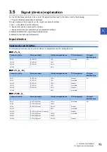
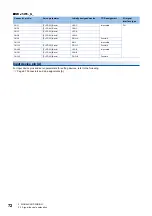
MR-J5W3-_G_
Input device pin [A]
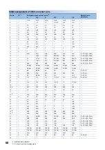
For input device pins and servo parameters for setting devices, refer to the following.
Page 67 Connectors and pin assignments [A]
Connector pin No.
Servo parameter
Initially assigned device
TPR assignment
I/O signal
interface type
CN3-1
[Pr. PD03] (C-axis)
LSP-C
Impossible
DI-1
CN3-2
[Pr. PD04] (C-axis)
LSN-C
CN3-7
[Pr. PD03] (A-axis)
LSP-A
CN3-8
[Pr. PD04] (A-axis)
LSN-A
CN3-9
[Pr. PD05] (A-axis)
DOG-A
Possible
CN3-10
EM2
Impossible
CN3-15
[Pr. PD05] (C-axis)
DOG-C
Possible
CN3-20
[Pr. PD03] (B-axis)
LSP-B
Impossible
CN3-21
[Pr. PD04] (B-axis)
LSN-B
CN3-22
[Pr. PD05] (B-axis)
DOG-B
Possible
Содержание MELSERVO-J5 MR-J5-G Series
Страница 1: ...MR J5 User s Manual Hardware MR J5 _G_ MR J5W_ _G_ MR J5 _A_ Mitsubishi Electric AC Servo System ...
Страница 2: ......
Страница 473: ...12 USING A FULLY CLOSED LOOP SYSTEM 12 7 Absolute position detection system 471 12 MEMO ...
Страница 477: ......


