3 SIGNALS AND WIRING
3.3 Explanation of power supply system
61
3
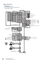
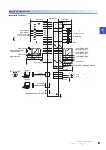
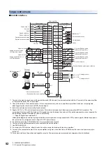
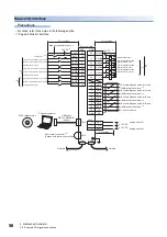
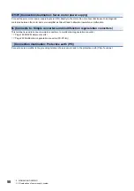
Wiring CNP1, CNP2, and CNP3
• For the wire sizes, refer to the following.
Page 217 Selection example of wires
• When wiring, remove the power connectors from the servo amplifier.
• Insert only one wire or ferrule into each wire insertion hole on each power connector.
To wire to CNP1, CNP2 and CNP3, use the servo amplifier power connectors that came with the amplifier.
Connector
■
MR-J5-10_ to MR-J5-100_
■
MR-J5-200_/MR-J5-350_
Connector Receptacle assembly
Applicable wire
Stripped length
[mm]
Open tool
Manufacturer
Size
Insulator OD
CNP1
06JFAT-SAXGDK-K7.5 (LA)
AWG 18 to 14
3.9 mm or less
9
J-FAT-OT-K
JST
CNP2
05JFAT-SAXGDK-K5.0 (LA)
CNP3
03JFAT-SAXGDK-K7.5 (LA)
Connector Receptacle assembly
Applicable wire
Stripped length
[mm]
Open tool
Manufacturer
Size
Insulator OD
CNP1
06JFAT-SAXGFK-XL (LA)
AWG 16 to 10
4.7 mm or less
11.5
J-FAT-OT-EXL
JST
CNP2
05JFAT-SAXGDK-H5.0 (LA)
AWG 18 to 14
3.9 mm or less
9
CNP3
03JFAT-SAXGFK-XL (LA)
AWG 16 to 10
4.7 mm or less
11.5
CNP2
CNP1
CNP3
CNP2
CNP1
CNP3
Содержание MELSERVO-J5 MR-J5-G Series
Страница 1: ...MR J5 User s Manual Hardware MR J5 _G_ MR J5W_ _G_ MR J5 _A_ Mitsubishi Electric AC Servo System ...
Страница 2: ......
Страница 473: ...12 USING A FULLY CLOSED LOOP SYSTEM 12 7 Absolute position detection system 471 12 MEMO ...
Страница 477: ......


