


6-532
Interference avoidance function
5Functions set with parameters
<4>Simulated component enable/disable: CAVSCA1 to 8
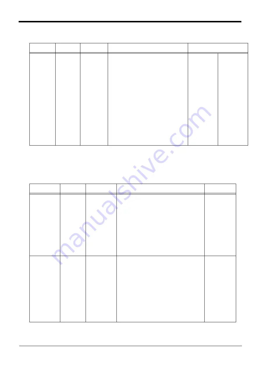
Table 5-34:Simulated component setting parameter (Robot arm: CAVSCA1 to 8)
2) Simulated components for hand
The parameters required to register a simulated hand are shown in
Table 5-35:Simulated component setting parameters (hand)
Parameter
Parameter
name
No. of arrays
No. of characters
Details explanation
Factory setting
Simulated
component
enable/disable
(robot arm)
CAVSCA1 to 8
Integer 3
Set whether to check (enable or disable)
interference for each simulated component. (Each
simulated component corresponds to the last digit
(1 to 8) of the parameter name.)
1st element: Enable/disable the setting
(0: Disable, 1: Enable)
2nd element: Set whether to let the interference
avoidance function to temporarily
disable interference checks during
jog operation. (Refer to
canceling the interference avoidance
function
.)
(0: Disable, 1: Maintain enabled
state)
Note) If interference is inevitable
during jog operation for
teaching, setting the simulated
hand or workpiece to “0:
Disable” can be convenient.
3rd element: Fixed to 0
RH-3/6/12/20FH
series:
CAVSCA1=1, 0, 0
CAVSCA2=0, 0, 0
CAVSCA3=1, 0, 0
CAVSCA4=1, 0, 0
CAVSCA5=1, 0, 0
CAVSCA6=1, 0, 0
CAVSCA7=1, 0, 0
CAVSCA8=1, 0, 0
RH-3FHR series
CAVSCA1=1, 0, 0
CAVSCA2=1, 0, 0
CAVSCA3=1, 0, 0
CAVSCA4=1, 0, 0
CAVSCA5=1, 0, 0
CAVSCA6=1, 0, 0
CAVSCA7=0, 0, 0
CAVSCA8=0, 0, 0
RV-F series:
CAVSCA1=1, 0, 0
CAVSCA2=1, 0, 0
CAVSCA3=1, 0, 0
CAVSCA4=1, 0, 0
CAVSCA5=1, 0, 0
CAVSCA6=0, 0, 0
CAVSCA7=0, 0, 0
CAVSCA8=0, 0, 0
Parameter
Parameter
name
No. of arrays
No. of characters
Details explanation
Factory setting
Hand number and
shape
(hand)
CAVKDH1 to 8
Integer 2
Set the hand number and shape of a simulated hand to
be registered. Up to eight simulated hand types can be
registered. (Each type corresponds to the last digit (1 to
8) of the parameter name.)
1st element: Hand number
Corresponds to the hand condition number
for changing the simulated component with
the
command.
0: Simulated component type set as default.
1 to 8: Hand condition number designated with the
command
2nd element: Shape
0: a sphere
1: a cylinder
Set all parameters
(CAVKDH1 to 8) to
“0, 0”.
Center position of
simulated compo-
nent
(hand)
CAVPSH1 to 8
Real number 6
For each simulated component, designate the center
position and pose of the simulated component from the
origin point of the
Mechanical interface coordinate
. (Each simulated component corresponds to the
last digit (1 to 8) of the parameter name.)
1st element: Distance in X axis direction (mm)
2nd element: Distance in Y axis direction (mm)
3rd element: Distance in Z axis direction (mm)
4th element: angle of rotation on X axis (degree)
5th element: angle of rotation on Y axis (degree)
6th element: angle of rotation on Z axis (degree)
Note) Calculate the rotation angle in order of Z
→
Y
→
X
axis. If shape is the sphere, setting of the rotation
angle is unnecessary.
Set all parameters
(CAVPSH1 to 8) to
“0, 0, 0, 0, 0, 0”.


