


Spline interpolation
Appendix-673
(B) Set the adjustment data.
If a controller is connected, the [Get current position] button will appear. When this button is clicked,
the robot's current position is imported as the adjustment data.
(C) Select the adjustment method and click the button.
(D) The adjusted path point data is displayed in the "Adjustment result list". The path point data, not
selected as an adjustment target, remains the unchanged.
(E) When the [OK] button is clicked, the adjustment results will be applied onto the path point data on the
Spline File Edit screen, and the Position adjustment screen will close.
When the [Cancel] button is clicked, the adjustment results will be discarded and the Position adjust-
ment screen will close.
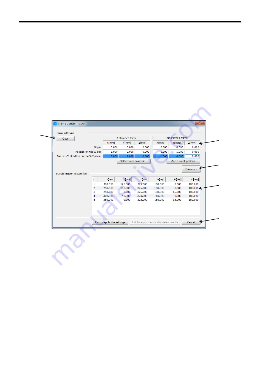
(2) Frame transformation function
When the menu [Tool]
→
[Frame transformation] is clicked, a screen for executing frame transformation
onto the path point data in the active Spline File Edit screen will open.
(Refer to
Page 624, "(5) Frame transformation"
for details on frame transformation.)
Fig.7-106:Frame transformation screen
■
Setting the coordinate system
In the (A) section of
, set the X, Y and Z axis coordinate values for the three positions (origin, posi-
tion on X axis, position in +Y direction on X-Y plane) that define the reference coordinate system and trans-
formed reference coordinate system.
For the reference coordinate system, the coordinate values can be selected from registered path point data
that appears when the [Select from point list...] button is clicked.
(A)
(B)
(C)
(D)
(E)


