


Detailed explanation of command words
4-257
[Explanation]
(1) In circular interpolation motion, a circle is formed with three given points, and robot moves along the cir-
cumference.
(2) The posture is interpolation from the start point to the end point; the reference point posture has no
effect.
(3) If the current position and start point do not match, the robot will automatically move with linear interpola-
tion (3-axis XYZ interpolation) to the start point.
(4) If paused during execution of a Mvr instruction and restarted after jog feed, the robot returns to the
interrupted position by JOINT interpolation and restarts the remaining circle interpolation.
The interpolation method (JOINT interpolation / XYZ interpolation) which returns to the interrupted
position can be changed by the "RETPATH" parameter.
(Refer to
Page 482, "5.10 Automatic return set-
)
(5) The direction of movement is in a direction that does not pass through the reference points.
(6) If the start point and end point structure flags differ when equivalent rotation (constant 2 = 0) is specified,
an error will occur at the execution.
(7) Of the three designated points, if any points coincide with the other, or if three points are on a straight
line, linear interpolation will take place from the start point to the end point. An error will not occur.
(8) If 3-axis XYZ is designated for the constant 2, the constant 1 will be invalidated, and the robot will move
with the taught posture.
(9) Constant 2 designates the posture interpolation type. 3-axis XYZ is used when carrying out interpolation
on the (X, Y, Z, J4, J5, J6) coordinate system, and the robot is to move near a particular point. The sin-
gular point passage function is supporting only certain models. Refer to
Page 509, "5.20 About singular
in details.
(10) Constant 2 designates the posture interpolation type. 3-axis XYZ is used when carrying out interpola-
tion on the (X, Y, Z, J4, J5, J6) coordinate system, and the robot is to move near a particular point.
(11) This instruction cannot be used in a constantly executed program.
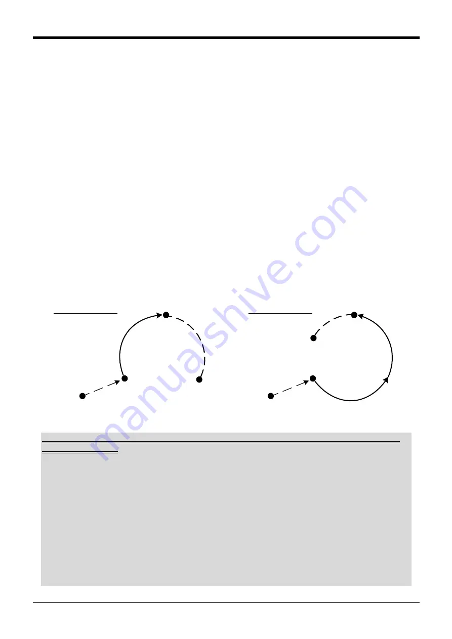
Fig.4-25:Example of circular interpolation motion path 2
P2
P1
P3
MVR2 P1, P2, P3
Moves by XYZ
interpolation (3-axis
XYZ interpolation)
P2
P1
P4
MVR2 P1, P2, P4
P_CURR
P_CURR
Moves by XYZ
interpolation (3-axis
XYZ interpolation)
Precautions for registration of position data after execution of linear (circular arc) interpolation for
vertical 5-axis robots
In the linear (circular arc) interpolation, the posture data at the operation start position and the posture
data at the movement target position are different by +180 degrees or -180 degrees or more, the robot
performs shortcut operation. For vertical 5-axis robots (RV-F series), the registered posture data is shown
at the movement target position, but the actual posture is deviated by +360 degrees or -360 degrees.
For example, when linear interpolation is performed from the 0-degree position to the +200-degree posi-
tion of the A axis, the posture data at the current position is shown as +200 degrees, but the robot oper-
ates to the -160-degree position.
When the position data is registered under such a condition, the posture data deviated by +360 or -360
degrees from the actual position is registered. Be careful when the position data is compensated after lin-
ear (circular arc) compensation movement for debugging operation (step feed, MS position movement) of
the program.
This phenomenon can be avoided by specifying the roundabout operation in the argument type of the lin-
ear (circular arc) interpolation, or by the servo OFF operation before the position data is registered.


