1
Table of Contents
1
System Overview································································ 1-1
1.1
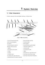
Main Components ........................................................................ 1-1
1.2
Definitions .................................................................................... 1-2
1.2.1
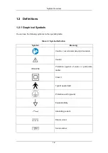
Graphical Symbols .............................................................. 1-2
1.2.2
Safety Notes ....................................................................... 1-4
1.2.3
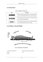
Definition of Slope/Tilt/Slide ................................................. 1-4
1.2.4
Definition of Permissible Overall Load ................................. 1-5
1.2.5
Definition of Central Position................................................ 1-5
1.2.6
Definition of 0 Position......................................................... 1-5
1.2.7
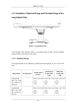
Definition of Standard Range and Extended Range of the
Longitudinal Slide......................................................................... 1-6
1.2.8
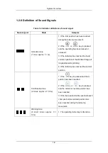
Definition of Sound Signals.................................................. 1-9
1.3
Warning Label............................................................................ 1-10
1.3.1
Central Position................................................................. 1-10
1.3.2
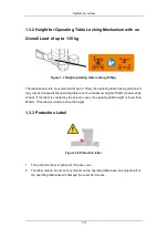
Height for Operating Table Locking Mechanism with an Overall
Load of up to 135 kg .................................................................. 1-11
1.3.3
Protection Label ................................................................ 1-11
1.3.4
No-sitting Label ................................................................. 1-12
1.3.5
Consulting Accompanying Documents Label ..................... 1-12
1.4
Intended Use ............................................................................. 1-13
1.5
Fundamental Safety Instructions ................................................ 1-14
1.5.1
Instructions against Personal Injury ................................... 1-14
1.5.2
Instructions against Property Damage ............................... 1-17
2
Daily Operations································································· 2-1
2.1
Power Supply Systems ................................................................ 2-1
2.1.1
AC Power............................................................................ 2-1
2.1.2
Battery................................................................................. 2-3
2.2
Potential Equalization................................................................... 2-4
2.2.1
Setting up Potential Equalization ......................................... 2-4
2.3
Control Units ................................................................................ 2-5
2.3.1
General ............................................................................... 2-5
2.3.2
Override Panel .................................................................... 2-5
2.3.3
Corded Hand Control (optional) ........................................... 2-9
2.3.4
Corded Hand Control with LCD (optional) .......................... 2-16
2.3.5
IR Remote Control with LCD (optional) .............................. 2-30
2.3.6
Foot Switch (optional)........................................................ 2-40
2.4
Patient Orientation ..................................................................... 2-41
2.4.1
Definition of Patient Orientation ......................................... 2-41
2.4.2
Setting the Patient Orientation ........................................... 2-42
Содержание HyBase 8300
Страница 1: ...Operator s Manual HyBase 8300 HyBase 8500 Operating Table ...
Страница 2: ......
Страница 84: ...This page is intentionally blank ...
Страница 106: ...This page is intentionally blank ...
Страница 110: ...This page is intentionally blank ...
Страница 122: ...This page is intentionally blank ...
Страница 132: ...This page is intentionally blank ...
Страница 142: ...This page is intentionally blank ...
Страница 150: ...Appendices 10 8 3 Back plate up down up 90 5 down 45 5 ...
Страница 153: ...Appendices 10 11 6 Dual joint head plate up down up 60 5 down 60 5 7 Reverse trendelenburg 20 5 Back plate down 20 5 ...
Страница 158: ...Appendices 10 16 3 Back plate up down up 90 5 down 45 5 ...
Страница 161: ...Appendices 10 19 6 Dual joint head plate up down up 60 5 down 60 5 7 Reverse trendelenburg 20 5 Back plate down 20 5 ...
Страница 167: ...Appendices 10 25 If you want to know more information please see the accessories brochure for details ...
Страница 175: ...This page is intentionally blank ...
Страница 176: ...P N 046 006753 00 2 ...


