background image

Daily Operations 

2-24 


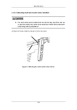
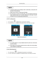
Figure 2-13 Tilt the operating table to right 


2.3.4.7  Module Recognition System (optional) 

1. 

As Figure 2-14 shows, when the leg plate is connected, the icon (A) will be displayed. 

2. 

As Figure 2-14 shows, when the leg plate is detached, the icon (B) will be displayed. 


 (

A


B


Figure 2-14 Module recognition 


Do  not  use  the  individual  adjustment  function  for  the  leg  plates  in 

conjunction with single-part accessory. 

Содержание HyBase 8300

Страница 1: ...Operator s Manual HyBase 8300 HyBase 8500 Operating Table ...

Страница 2: ......

Страница 3: ...ights or patents and does not convey any license under the patent rights or copyright of Mindray or of others Mindray intends to maintain the contents of this manual as confidential information Disclosure of the information in this manual in any manner whatsoever without the written permission of Mindray is strictly forbidden Release amendment reproduction distribution rental adaption and translat...

Страница 4: ...d performance of this device only if all installation operations expansions changes modifications and repairs of this device are conducted by Mindray authorized personnel the electrical installation of the relevant room complies with the applicable national and local requirements and the device is used in accordance with the instructions for use This device must be operated by skilled trained clin...

Страница 5: ...function or damage caused by improper operation or repair by unqualified or unauthorized service people Malfunction of the device or part whose serial number is not legible enough Others not caused by device or part itself Return Policy Return Procedure In the event that it becomes necessary to return this device or part of this device to Mindray the following procedure should be followed Return a...

Страница 6: ...o Ltd Address 666 Middle Zhengfang Road Jiangning 211100 Nanjing Jiangsu P R China Tel 86 25 66082666 Fax 86 755 26582680 26666 EC Representative Shanghai International Holding Corp GmbH Europe Address Eiffestrasse 80 20537 Hamburg Germany Tel 0049 40 2513175 Fax 0049 40 255726 ...

Страница 7: ...3 Protection Label 1 11 1 3 4 No sitting Label 1 12 1 3 5 Consulting Accompanying Documents Label 1 12 1 4 Intended Use 1 13 1 5 Fundamental Safety Instructions 1 14 1 5 1 Instructions against Personal Injury 1 14 1 5 2 Instructions against Property Damage 1 17 2 Daily Operations 2 1 2 1 Power Supply Systems 2 1 2 1 1 AC Power 2 1 2 1 2 Battery 2 3 2 2 Potential Equalization 2 4 2 2 1 Setting up P...

Страница 8: ...al 3 3 3 3 Patient Positioning with an Overall Load of up to 135 kg 3 8 3 3 1 General 3 8 4 Cleaning and Disinfection 4 1 4 1 General 4 1 4 1 1 Recommended Cleaning Agents and Disinfectants 4 2 4 1 2 Forbidden Cleaning Agents and Disinfectants 4 2 4 2 Cleaning 4 3 4 2 1 Preparations 4 3 4 2 2 Cleaning Procedure 4 3 4 3 Disinfection 4 5 4 3 1 General 4 5 4 3 2 Disinfection Procedure 4 5 4 4 Table P...

Страница 9: ...and Disinfection 7 10 7 6 1 Cleaning 7 10 7 6 2 Disinfection 7 10 8 Anesthesia Frame 8 1 8 1 Intended Use 8 1 8 2 Heavy Anesthesia Frame 8 2 8 2 1 Specifications 8 2 8 2 2 Components 8 2 8 2 3 Installation and Use 8 3 8 3 Light Anesthesia Frame 8 4 8 3 1 Specifications 8 4 8 3 2 Components 8 4 8 3 3 Installation and Use 8 4 8 4 U shaped Anesthesia Frame 8 6 8 4 1 Specifications 8 6 8 4 2 Component...

Страница 10: ...Cleaning and Disinfection 9 7 9 4 1 Cleaning 9 7 9 4 2 Disinfection 9 7 9 4 3 Cleaning Disinfecting Pad 9 8 9 4 4 Cleaning Fastening Strap 9 9 10 Appendices 10 1 A Technical Specifications 10 1 A 1 Classification 10 1 A 2 Environment 10 3 A 3 Load 10 5 A 4 Specifications 10 7 A 5 Accessories 10 23 A 6 EMC 10 26 B Index 10 31 ...

Страница 11: ...g plate optional 8 Locking handle leg plate left right 9 Release button leg plate 10 Potential equalization pin 11 Bellows 12 Override panel 13 Connection for foot switch 14 Connection for USB 15 Castor 16 Base 17 Column 18 Connection for corded hand control 19 Infrared receiver 20 Locking button extension plate 21 Locking button upper back plate 22 Locking button dual joint head plate 23 Release ...

Страница 12: ...s on the operating table Table 1 1 Symbol Definition Symbol Meaning Caution consult accompanying documents Caution IPX4 IPX8 Protection against of water or particulate matter Class II Type B applied part Protective earth ground Equipotentiality Alternating current Direct current Serial number ...

Страница 13: ...l indicates that this product should not be treated as household waste By ensuring that this product is disposed of correctly you will help prevent bringing potential negative consequences to the environment and human health For more detailed information with regard to returning and recycling this product please consult the distributor from whom you purchased the product ESD warning Labeling for C...

Страница 14: ...use personal injury Read the statement below the symbol The statement alerts you to possible property damage Read the statement below the symbol The statement alerts you to information that requires your attention 1 2 3 Definition of Slope Tilt Slide Figure 1 2 Definition of slope tilt slide 1 Trendelenburg head down 2 Reverse trendelenburg foot down 3 Slope 4 Tilt 5 Slide 5 1 2 4 3 ...

Страница 15: ...ceeding an overall load of 230kg may only be operated if the longitudinal slide of the operating table is in the central position The operating table is in the central position when the table top longitudinal slide stops and a sound signal 1 tone is heard Press or again to continue sliding the table top Figure 1 3 Central position label 1 2 6 Definition of 0 Position 1 The 0 position Tilt is cance...

Страница 16: ...tion of the head 1 2 7 1 Standard Range The longitudinal slide can be adjusted by pressing the following key s on one of the control units Adjustments Override Panel Corded Hand Control Corded Hand Control with LCD IR Remote Control with LCD Longitudinally slide the table top toward the head end Press and hold Press and hold Press and hold Longitudinally slide the table top toward the foot end Pre...

Страница 17: ...slide the table top stops and a sound signal 1 tone is heard The table top can be moved further 170mm toward the head end by pressing the following keys on the control units Table 1 3 Extended Range Adjustments Override Panel Corded Hand Control Corded Hand Control with LCD IR Remote Control with LCD Longitudinally slide the table top toward the head end Press and hold Press and hold Press and hol...

Страница 18: ...tion keys except for the up down key will also change accordingly As the figure below shows the slide protection icon will be displayed on the corded hand control with LCD and or the IR remote control with LCD when the key is pressed in the extended range Figure 1 5 Slide protection icon ...

Страница 19: ... has reached the head end limit position of the standard range of longitudinal slide 230mm 4 If the table top has reached the central position Confirmation tone 2 tones approx 2 0 5s 1 If the key is pressed and the 0 position has been reached 2 If the or key is pressed and the normal or reverse position has been reached 3 If the flex position re flex position beach chair position memorized positio...

Страница 20: ... if the longitudinal slide of the operating table is in the central position 3 The operating table is in the central position when the table top longitudinal slide stops and a sound signal 1 tone is heard 4 Press the or again to continue sliding the table top If the central position is reached with the longitudinal slide of the table top adjustment is stopped and an alarm sounds To continue slidin...

Страница 21: ...ased if the operating table is set to a maximum height of 940mm lower edge of pad If the label is covered by the column cover the operating table height is lower than 940mm If the label is visible reduce the height 1 3 3 Protection Label Figure 1 8 Protection label 1 The protection label is located at the base cover 2 The label means Do not put any objects on the operating table base Any objects l...

Страница 22: ...anying Documents Label Figure 1 10 Consulting accompanying documents label 1 The label is located at the hooks of the dual joint head plate and dual joint leg plate 2 The label means Consult accompanying documents Be sure to install and remove the dual joint head plate and or dual joint leg plate strictly as instructed in the manual See chapter 2 5 1 1 2 5 1 2 2 5 3 1 and 2 5 3 2 for details ...

Страница 23: ...of this manual are based on the full configuration of the operating table Some of them can not apply to your operating table Use your operating table according to the actual configuration If you have any questions contact the customer service department authorized by Nanjing Mindray or your local distributor The operating table is to be operated by trained personnel only Be sure to archive the tra...

Страница 24: ... are neither the operator s feet nor any objects underneath the base Otherwise it can cause personal injury or property damage Before lowering the table top be sure to observe that there are neither the operator s feet nor any objects on the base cover underneath the column Otherwise it may get pinched or crushed The operating table can only be adjusted when it is locked If not only the trendelenb...

Страница 25: ...le top is in the best balanced state 0 position table top horizontal and slid to the central position Do not transfer the patient otherwise Placing the patient improperly can tip over the operating table Be sure to place the patient in the right direction Do not place the patient s trunk on the leg plates When placing the patient make sure the patient s center of gravity is as close to the column ...

Страница 26: ...ents listed in this manual Make sure the ground is level before installing the operating table If the integrity of the external protective conductor in the installation or its arrangement is in doubt run the operating table from its internal battery When the operating table is not in use make sure it is placed on a level ground the castors are properly locked the table top is in the 0 position and...

Страница 27: ...he operator s manual thoroughly Used operating tables including their batteries and accessories should be disposed of in compliance with local governmental or hospital regulations 1 5 2 Instructions against Property Damage Do not modify the operating table or accessories without authorization of Nanjing Mindray Make sure the operating table is serviced or maintained by the authorized personnel onl...

Страница 28: ...ng table make sure the accessories or the surgical drapes are not jammed by the joints If your operating table has the longitudinal slide function its leg plates and head plate are not interchangeable When the operating table is not in use make sure its castors are locked and table top is in the best rest state table top slid to the limit of the foot end and descended to the lowest position Do not...

Страница 29: ...y 2 1 1 AC Power Damaged cables must be replaced immediately To avoid risk of electric shock the operating table must only be connected to the supply mains with protective earth Before locking the operating table be sure to observe that there are neither the power cord nor any objects underneath the base Otherwise it can cause personal injury or property damage Unplug the operating table before mo...

Страница 30: ...d into a power outlet 5 The AC indicator at the corded hand control is on and green when the operating table is connected to the mains supply See chapter 2 3 3 2 for details When connecting and removing the mains cable observe the correct order of the procedure Figure 2 1 Power connector 1 Cover 2 Power connector 2 1 1 2 Detaching the Power Cord 1 Detach the plug from the socket at the power point...

Страница 31: ...tery assembly 2 1 2 1 Charging the Battery 1 Locate the power cord delivered with the operating table 2 Lift the cover 1 3 Plug the non pronged end of the power cord into the power connector 2 4 Plug the pronged end of the power cord into a power outlet 5 The battery indicator at the corded hand control is blinking and green when the battery is being charged See chapter 2 3 3 2 for details Figure ...

Страница 32: ...een electrical devices Make sure it is connected to a potential equalization point within the operating room before using the operating table 2 2 1 Setting up Potential Equalization 1 Connect the equalization cable to the equalization pin 1 on the operating table 2 Connect the other end of the potential equalization cable to the operating room s potential equalization point 1 ...

Страница 33: ...l motions at the operating table will be stopped immediately and will resume only after none of the control units has been activate for at least 2 seconds 2 3 2 Override Panel 2 3 2 1 Keys You can use the override panel to turn on the override panel lock unlock the castors raise lower the table top obtain the trendelenburg reverse trendelenburg positions tilt the table top to left right raise lowe...

Страница 34: ... to right 18 Tilt to left You can 1 Press and hold for 10 seconds to lock the castors 2 Press and hold for 10 seconds to unlock the castors 3 Press and hold 9 11 or 15 to raise the table top back plate both leg plates 4 Press and hold 10 12 or 16 to lower the table top back plate both leg plates 5 Press and hold to tilt the table top left 6 Press and hold to tilt the table top right 7 Press and ho...

Страница 35: ...hen the table is connected to the mains The override panel is intended for emergency use only The override panel employs the two key control mode To use the panel press both the Power On key and the desired functional key simultaneously 2 3 2 2 Indicators There are five indicators on the override panel AC indicator battery indicator power indicator locking indicator and unlocking indicator which h...

Страница 36: ...s not jammed The connections for corded hand control 1 and the foot switch 3 are located next to the override panel on the left and right The service interface 2 is underneath the override panel Figure 2 5 Connections 1 Corded hand control connection 2 Service interface 3 Foot switch connection Connection procedure 1 Open protective cover 2 Insert the plug firmly 1 2 3 ...

Страница 37: ...late obtain the flex re flex position obtain the beach chair position longitudinally slide the table top toward the head foot end optional obtain the 0 position levels the table top and slides it to the central position Do not use the individual adjustment function for the leg plates in conjunction with single part accessory Be sure to remove any potential hindrances before adjusting the operating...

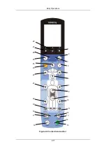
Страница 38: ...Daily Operations 2 10 Figure 2 6 Corded hand control 1 2 3 4 23 5 29 6 27 25 7 24 8 22 9 10 11 21 20 12 19 13 18 14 15 17 16 26 30 28 ...

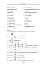
Страница 39: ...left 25 Trendelenburg position head down 26 Table top up 27 Normal position indicator 28 Normal position 29 Flex position 30 Beach chair position You can 1 Press any key to turn on the corded hand control and recall the operating 2 Press to turn on off the operating table 3 Press and hold to obtain the 0 position 4 Press to lock the castors 5 Press to unlock the castors 6 Press and hold or to rais...

Страница 40: ...re flex position 19 Press to obtain the beach chair position After adjusting the operating table be sure to switch off the hand control Each time before using the operating table check all functions by pressing every functional key for 2 to 3 seconds Make sure all the keys can work normally Do not use the damaged operating table When adjusting the operating table make sure the cord of the hand con...

Страница 41: ...f Power indicator Orange and flashing or green and flashing The operating table may malfunction Green The operating table is AC powered AC indicator Off The operating table is disconnected from mains supply Green The batteries function normally Green and flashing The batteries are charging Battery indicator Red and flashing The batteries are low Normal position indicator Green The operating table ...

Страница 42: ...ilt to left right Back plate up down Flex re flex position If the 0 position function is activated the table top automatically levels and slides to the central position Closely watch the table top movement and release the key when the table top no longer moves 2 3 3 4 Error Indication When the operating table or the corded hand control is broken all the indicators are blinking orange Please contac...

Страница 43: ...rol which is attached to the side rail may slip off the side rail or catch the cable only corded hand control and corded hand control with LCD during table top adjustment As Figure 2 7 shows attach the bracket 1 to the side rail 2 Figure 2 7 Attaching the hand control to the side rail 1 2 ...

Страница 44: ...late left right leg plate obtain the flex re flex position longitudinally slide the table top toward the head foot end optional obtain the 0 position levels the table top and slides it to the central position Do not use the individual adjustment function for the leg plates in conjunction with single part accessory Be sure to remove any potential hindrances before adjusting the operating table Othe...

Страница 45: ...Daily Operations 2 17 Figure 2 8 Corded hand control 1 28 1 26 2 3 27 4 6 23 5 22 21 7 8 9 10 20 11 19 13 18 14 15 17 16 25 24 12 ...

Страница 46: ...le top up 25 Normal position 26 Normal position indicator 27 Flex position choose 28 Menu confirm You can 1 Press any key to turn on the corded hand control and recall the operating 2 Press to turn on off the operating table 3 Press and hold to obtain the 0 position 4 Press to lock the castors 5 Press to unlock the castors 6 Press and hold or to raise lower the right leg plate 7 Press and hold or ...

Страница 47: ...le be sure to switch off the hand control Each time before using the operating table check all functions by pressing every functional key for 2 to 3 seconds Make sure all the keys can work normally Do not use the damaged operating table When adjusting the operating table make sure the cord of the hand control is not jammed by the joints When the corded hand control has been idle for about 90 secon...

Страница 48: ...ng table is switch on Off The operating table is switch off Power indicator Orange and flashing or green and flashing The operating table may malfunction Normal position indicator Green The operating table is in normal position Reverse position indicator Green The operating table is in reverse position Locking indicator Orange The castors are locked Unlocking indicator Red The castors are unlocked...

Страница 49: ...ble top icon 6 Re flex position back icon 7 Confirm icon 8 Flex position select icon 9 Locking icon 10 Reverse position icon Table 2 3 Status icon definitions of corded hand control with LCD Name Icon State Definition AC icon The operating table is AC powered Static Battery capacity of the operating table Dynamic The batteries are charging Battery icon operating table Red and blinking The batterie...

Страница 50: ...con is displayed in the status bar when the castors are locked Figure 2 10 Locking icon The operating table can only be adjusted when the castors are locked lock function is active If the castors are not locked unlock function is active then only the slope can be adjusted in emergencies 2 3 4 5 Unlocking Icon 1 The unlocking icon will be displayed when the unlocking key is pressed 2 Then the unloc...

Страница 51: ...lope can be adjusted in emergencies 3 The following icon will be displayed if the operating table is unlocked and sloped Figure 2 12 Slope the operating table unlocking 2 3 4 6 Tilting the Operating Table When the operating table is adjusted the screen on the controller will display the corresponding movement and angle As Figure 2 13 shows the screen displays sign during tilting operating table to...

Страница 52: ...l 1 As Figure 2 14 shows when the leg plate is connected the icon A will be displayed 2 As Figure 2 14 shows when the leg plate is detached the icon B will be displayed A B Figure 2 14 Module recognition Do not use the individual adjustment function for the leg plates in conjunction with single part accessory ...

Страница 53: ...nction applies to the following movements Trendelenburg reverse trendelenburg position Tilt to left right Back plate up down Flex re flex position Figure 2 15 If the 0 position function is activated the table top automatically levels and slides to the centre position Closely watch the table top movement and release the key when the table top no longer moves 2 3 4 9 Error Icon If the error icon is ...

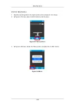
Страница 54: ...ons can be stored The first position is preset the beach chair position and it cannot be revised by users If users want to store other positions see chapter 2 3 4 10 2 for details 2 3 4 10 1 Recall Position 1 As Figure 2 17 shows press confirm button to enter the menu Figure 2 17 ...

Страница 55: ...d press the confirm button Figure 2 18 Menu 3 As Figure 2 19 shows press the choose button to choose the position Figure 2 19 Select the position 4 As Figure 2 20 shows press and hold the confirm button until a sound signal 2 tones is heard Figure 2 20 Recalling the position ...

Страница 56: ... the operating table to the object position and see chapter 2 3 4 1 shows 2 As Figure 2 21 shows press confirm button to enter the menu Figure 2 21 Store position 3 As Figure 2 22 shows choose the Store position and press the confirm button Figure 2 22 Menu ...

Страница 57: ...d signal two tones Figure 2 23 Confirm 5 As Figure 2 24 shows the icon will back to the Initial interface after the position is stored Figure 2 24 Initial interface The factory settings can be used only for customer service engineer authorized by Nanjing Mindray 2 3 4 11 Attaching the Hand Control to the Side Rail See chapter 2 3 3 5 for details ...

Страница 58: ...ng table and the associated IR remote control are marked by adhesive code labels 1 The adhesive code labels are affixed to the operating table column next to the IR receiver 2 The adhesive labels are affixed to the back of the IR remote control with LCD The adhesive code labels bear a number from 0 to 9 1 left 0 1 2 9 2 right 0 1 2 9 Examples of preset IR system codes Markings 1 5 3 0 2 3 8 9 Figu...

Страница 59: ... plate obtain the flex re flex position optional longitudinally slide the table top toward the head foot end optional obtain the 0 position levels the table top and slides it to the central position Do not use the individual adjustment function for the leg plates in conjunction with single part accessory Be sure to remove any potential hindrances before adjusting the operating table Otherwise it c...

Страница 60: ...Daily Operations 2 32 Figure 2 26 Corded hand control 20 6 23 7 22 2 21 1 3 19 4 18 5 16 8 15 9 14 10 13 11 12 17 ...

Страница 61: ...You can 1 Press any key to turn on the corded hand control and recall the operating 2 Press to turn on off the operating table 3 Press and hold to obtain the 0 position 4 Press to lock the castors 5 Press to unlock the castors 6 Press and hold or to raise lower the right leg plate 7 Press and hold or to raise lower the left leg plate 8 Press and hold 5 8 or 20 to raise the table top back plate bot...

Страница 62: ...ble does not respond to the command even though the function key is completely depressed either re aim the hand control or move to a slightly different transmission position In such cases the infrared receiver at the column is being blocked by a person s body When the IR remote control with LCD has been idle for about 90 seconds it will be switched off automatically If the table top is sloped tren...

Страница 63: ...icon 9 Locking icon 10 Reverse position icon 11 Status bar Table 2 4 Status icon definitions of IR remote control with LCD Name Icon State Definition AC icon The operating table is AC powered Static Battery capacity of the operating table Dynamic The batteries are charging Battery icon operating table Red and blinking The batteries are low Static Battery capacity of the IR remote control with LCD ...

Страница 64: ...able 2 3 5 5 Locking Icon 1 The locking icon is displayed when pressing the locking key 2 Then the locking icon is displayed in the status bar when the castors are locked Figure 2 28 Locking icon The operating table can only be adjusted when the castors are locked lock function is active If the castors are not locked unlock function is active then only the slope can be adjusted in emergencies 2 3 ...

Страница 65: ...when the castors are locked lock function is active If the castors are not locked unlock function is active then only the slope can be adjusted in emergencies 3 The following icon will be displayed if the operating table is unlocked and sloped Figure 2 30 Slope the operating table unlocking ...

Страница 66: ...ure 2 31 Error icon 2 3 5 8 Mobile Charging Station for IR Remote Control with LCD optional 2 3 5 8 1 Charging the Battery in the IR Remote Control with LCD 1 Connect the mobile charging station to the mains 2 Slide the IR remote control with LCD 1 oriented correctly into the charging station 2 until the lower end of the IR remote control with LCD makes contact with the stop ...

Страница 67: ...icator definitions of IR remote control with LCD Indicator State Definition Red The mobile charging station is connected with the mains Power indicator Green and flashing The batteries are charging The IR remote control with LCD is reliably placed if the power indicator of the mobile charging station is green and flashing 2 3 5 9 Attaching the Hand Control to the Side Rail See chapter 2 3 3 5 for ...

Страница 68: ...ot switch see the foot switch operator s manual for details Be sure to use the foot switch according to the foot switch operator s manual If the operating table is set to reverse position the components controlled by the buttons for the back plate and leg plate are reversed ...

Страница 69: ...on prior to making any adjustment The patient orientation is indicated on the hand control by the normal indicator or the reverse position indicator The patient orientation depends on the position of the patient on the table top with regard to the operating table base 2 4 1 1 Normal Patient Orientation As the Figure 2 33 shows the upper part of the patient s body is located above the operating tab...

Страница 70: ...rientation 2 4 2 Setting the Patient Orientation Depending on the position of the patient the patient orientation needs to be set so that the adjustment function can be carried out correctly 1 Press the button to obtain the normal position and the normal position indicator is green 2 Press the button to obtain the reverse position and the reverse position indicator is green 1 ...

Страница 71: ... not use it beyond this limit If accessories are used make sure the weights of the accessories installed on the dual joint head plate and of the patient s head add up no more than 15kg Do not install such devices as arm boards anesthesia frames and infusion holders on the dual joint head plate Otherwise the dual joint head plate can move unexpectedly When using the dual joint head plate be sure to...

Страница 72: ... Dual joint Head Plate 1 Hold the dual joint head plate with both hands and push the locking button with fingers 2 As Figure 2 35 shows lift the dual joint head plate and pull it out A B Figure 2 35 Removing the dual joint head plate Button ...

Страница 73: ... The head plate is reliably installed if you hear a click 3 Make sure the hooks are hung fully as figure 2 36 B shows 4 Pull the dual joint head plate to check whether it has been installed properly A B Figure 2 36 Installing the dual joint head plate The label means be sure to install and remove the dual joint head plate strictly as instructed in the manual Hook Installation groove ...

Страница 74: ...d the bracket 4 Pull the dual joint head plate to check whether it has been adjusted properly 5 Pull the release button 3 with one hand and raise or lower the upper plate 4 to the desired position with the other hand 6 Release the upper plate 4 and the release button 3 Figure 2 37 Adjusting the dual joint head plate When lowering the dual joint head plate be sure to do it slowly and smoothly Do no...

Страница 75: ... not pinch yourself The maximum load of the extension plate is 55kg Do not use it beyond this limit If accessories are used make sure the weights of the accessories installed on the extension plate and of the patient s back add up no more than 55kg When using the extension plate be sure to cover it with a sterile surgical drape Each time before using the pad check it carefully Do not use the worn ...

Страница 76: ...ving the extension plate 2 5 2 2 Installing Extension Plate 1 Hold the extension plate with both hands 2 As Figure 2 39 A shows hang the extension plate onto the installing grooves The extension plate is reliably installed if you hear a click 3 Make sure the hooks are hung fully as Figure 2 39 B shows 4 Pull the extension plate to check whether it has been installed properly Button ...

Страница 77: ...ge Exercise caution when removing installing the dual joint leg plate Do not pinch yourself Placing the patient improperly can tip over the operating table Be sure to place the patient in the right direction Do not place the patient s trunk on the dual joint leg plate When using the dual joint leg plate be sure to cover it with a sterile surgical drape The maximum load of the dual joint leg plate ...

Страница 78: ...mn or the operating table base Make sure that the dual joint leg plates are not crossed on top of each other before adjusting the leg plates for the horizontal position Otherwise it can cause personal injury and or property damage Each time before using the pad check it carefully Do not use the worn or damaged pad Be sure to use the pad provided by Nanjing Mindray only 2 5 3 1 Removing Dual joint ...

Страница 79: ...The leg plate is reliably installed if you hear a click 3 Make sure the hooks are hung fully as Figure 2 41 B shows 4 Pull the dual joint leg plate to check whether it has been installed properly A B Figure 2 41 Installing the dual joint leg plate The label means be sure to install and remove the dual joint leg plate strictly as instructed in the manual Hooks Installation groove ...

Страница 80: ...eg plate up down See chapter 2 3 3 1 2 3 4 1 and 2 3 5 2 for details Before adjusting the dual joint leg plate make sure nothing is under it To move the dual joint leg plate left right 1 Loose the handle 1 Figure 2 42 Loosing the handle of the dual joint leg plate 2 Adjust the dual joint leg plate left right to the desired position Figure 2 43 Moving dual joint leg plate left right 3 Tighten the h...

Страница 81: ...nal See the head plate operator s manual for details 2 5 5 Upper Back Plate optional The upper back plate is optional See the upper back plate operator s manual for details 2 5 6 Leg Plate optional The leg plates are optional See the leg plate operator s manual for details ...

Страница 82: ...d pad and cause hygienic problems When disinfecting the patient s skin make sure the disinfectant does not accumulate under the patient 2 6 1 Foam Pad 2 6 1 1 Installing Pad 1 Lay the pad on the table 2 Make sure that the Velcro strap loop on the pad is fully aligned with that on the table top hook 3 Check whether the pad is reliably installed Figure 2 44 Installing pad Velcro strap ...

Страница 83: ... only use the cleaning agents and methods recommended in this manual to clean the pad Otherwise it can cause personal injury and or property damage Each time before using the pad check it carefully Do not use the worn or damaged pad When using the pad be sure to cover it with a sterile surgical drape Pad should be stored lying flat and horizontal When removing the pad be sure to grasp it with both...

Страница 84: ...This page is intentionally blank ...

Страница 85: ...s used If the load on the operating table exceeds 230kg half yearly maintenance is required Never extend the swivel castors of the mobile operating table if the overall load exceeds 230kg unlock function is prohibited Otherwise it can cause the operating table tipping When the patient positioning at an overall load between 230kg and 460kg please observe the following functional restrictions 1 Lock...

Страница 86: ...be used for adiposity surgery taking into consideration the required supports Figure 3 1 Normal position 230kg to 460kg of over load 1 Head plate 2 Upper back plate 3 4 Dual joint head plate 5 Dual joint leg plate 6 Leg plate Max 510mm Max 680mm 1 2 4 2 5 6 ...

Страница 87: ...d on the operating table and of the patient add up no more than the permissible overall load Only use accessory which is approved for its share of the load imposed by the weight of a patient The pictorial views in this chapter show the recommended accessory for patient positioning considering the patient weight Refer to chapter A 6 for the complete list of the accessories used ...

Страница 88: ...k normal patient orientation Operating table is in the lowest height maximum extension of the table top head end 760mm maximum extension of the table top foot end 930mm Figure 3 2 Normal position 135kg to 230kg of overall load unlock 1 Head plate 2 Upper back plate 3 Extension plate 4 Dual joint head plate 5 Dual joint leg plate 6 Leg plate Max 760mm Max 930mm 1 2 3 4 2 3 5 6 4 1 2 2 5 6 ...

Страница 89: ...est height maximum extension of the table top head end 930mm maximum extension of the table top foot end 650mm Figure 3 3 Reverse position 135kg to 230kg of overall load unlock 1 Head plate 2 Upper back plate 3 Extension plate 4 Dual joint head plate 5 Dual joint leg plate 6 Leg plate Max 650mm Max 930mm 5 3 6 5 6 4 1 2 2 ...

Страница 90: ...n of the table top head end 760mm maximum extension of the table top foot end 930mm Figure 3 4 Normal position 135kg to 230kg of overall load lock 1 Head plate 2 Upper back plate 3 Extension plate 4 Dual joint head plate 5 Dual joint leg plate 6 Leg plate Max 760mm Max 930mm 1 2 3 4 2 3 5 6 4 1 2 2 5 6 ...

Страница 91: ...ension of the table top head end 930mm maximum extension of the table top foot end 650mm Figure 3 5 Reverse position 135kg to 230kg of overall load lock 1 Head plate 2 Upper back plate 3 Extension plate 4 Dual joint head plate 5 Dual joint leg plate 6 Leg plate Max 650mm Max 930mm 5 3 6 5 6 4 1 2 2 ...

Страница 92: ...n the operating table and of the patient add up no more than the permissible overall load Only use accessory which is approved for its share of the load imposed by the weight of a patient The pictorial views in this chapter show the recommended accessory for patient positioning considering the patient weight Refer to chapter A 6 for the complete list of the accessories used ...

Страница 93: ...mal patient orientation maximum extension of the table top head end 760mm maximum extension of the table top foot end 930mm maximum height bottom edge of pad 940mm Figure 3 6 Normal position up to an overall weight of 135kg unlock 1 Head plate 2 Upper back plate 3 Extension plate 4 Dual joint head plate 5 Dual joint leg plate 6 Leg plate Max 760mm Max 930mm 1 2 3 4 2 3 5 6 4 1 2 2 5 6 ...

Страница 94: ...head end 1130mm maximum extension of the table top foot end 760mm maximum height bottom edge of pad 940mm Figure 3 7 Reverse position up to an overall weight of 135kg unlock 1 Head plate 2 Upper back plate 3 Extension plate 4 Dual joint head plate 5 Dual joint leg plate 6 Leg plate Max 1130mm Max 760mm 5 2 3 6 2 3 1 4 5 6 4 1 2 2 ...

Страница 95: ...tension of the table top foot end 1180 mm Figure 3 8 Normal position up to an overall weight of 135kg lock 1 Head plate 2 Upper back plate 3 Extension plate 4 Dual joint head plate 5 Dual joint leg plate 6 Leg plate 7 Carbon fiber cardiac operating plate 8 Carbon fiber orthopedic extension device 3 Max 1180mm Max 850mm 1 2 3 4 2 5 6 4 1 2 2 5 6 7 8 ...

Страница 96: ...nd 1130 mm maximum extension of the table top foot end 1180 mm Figure 3 9 Reverse position up to an overall weight of 135kg lock 1 Head plate 2 Upper back plate 3 Extension plate 4 Dual joint head plate 5 Dual joint leg plate 6 Leg plate 7 Carbon fiber cardiac operating plate 8 Max 1130mm Max 1180mm 5 2 3 6 2 3 1 4 5 6 4 1 2 2 7 ...

Страница 97: ... the cleaning agents or disinfectants containing alcohol where such medical devices as electrosurgical units defibrillators or defibrillator monitors can be used Otherwise it can cause fire and or explosion hazards Particles of grime may become encapsulated and lead to the product not reaching the desired germ reduction after disinfection Before disinfection the product must be cleaned thoroughly ...

Страница 98: ... the cleaning agent disinfectant directly into the joints or gaps Do not use high pressure cleaning devices Do not use scouring agents Do not use water containing metal particles any metal tools such as wire brushes or steel wool or products containing hydrochloric acid to clean the operating table 4 1 2 Forbidden Cleaning Agents and Disinfectants Disinfectants containing alcohol e g hand disinfec...

Страница 99: ...lean water 5 Ensure that the product is free of detergent residues 6 Dry product with a dry absorbent and lint free cloth This will help to reduce pathogen growth on the product s surface 7 Disinfect the product after every cleaning Exercise caution for the gaps when cleaning or disinfecting the table top Otherwise you can be pinched In the event of very dirty product surfaces carry out an additio...

Страница 100: ...product with a dry lint free cloth Do not spray cleaning agent directly into the joints or gaps and never use a high pressure cleaning unit Cleaning causes lubricants to be flushed out of the product Re lubricate the product according to the lubrication instructions ...

Страница 101: ...e times Exceeding the specified exposure time of the disinfectant may damage the surfaces Remove disinfectant residues with a cloth dipped in clean water Then dry the product with a dry lint free cloth 4 3 2 Disinfection Procedure 1 Disinfect wipe or spray the product in accordance with the instructions of the detergent manufacturer each time after the product is cleaned 2 Thoroughly wipe off the ...

Страница 102: ...sive capacity of the pad on the hard paper plate will be reduced if the hook tapes of the Velcro fastener on the hard paper plate are contaminated To avoid damage to the hook tapes we recommend the removal of contamination using a plastic comb Pad should be stored lying flat and horizontal When removing the pad be sure to grasp it with both hands Before installing the pad make sure that the table ...

Страница 103: ...Cleaning and Disinfection 4 7 4 4 2 Disinfection Do not use the disinfectants containing alcohol to clean the pad Disinfectants containing aldehydes are recommended ...

Страница 104: ...Cleaning and Disinfection 4 8 4 5 Swivel Castor 1 Turn the swivel castors outward 2 Use a cloth dipped in a surface disinfectant to clean the swivel castors ...

Страница 105: ...cables 7 Are all table top movements functional 5 1 2 Maintenance 1 Complete electrical safety inspections should be conducted every year by personnel authorized by Nanjing Mindray 2 It is recommended that the operating table be serviced by professionals every year 3 It is recommended that the hydraulic oil be replaced by professionals every 5 years The operating table may be used only when proper...

Страница 106: ...This page is intentionally blank ...

Страница 107: ...ment authorized by Nanjing Mindray for help Unauthorized device servicing is not allowed Device servicing is to be performed by personnel authorized by Nanjing Mindray only Unauthorized device servicing can cause personal injury and or property damage Device servicing should be strictly based on technical data supplied by Nanjing Mindray If you are in need of more technical data contact the custom...

Страница 108: ...e 1 Check whether the mains supply is connected 2 Check whether the battery is sufficiently charged 3 Check whether the power switch is on 4 Press and hold the key on the override panel for 3 seconds When you press the key the table top can not be slid and a sound signal one tone is heard The table top is in the extended range Press and hold The battery indicator is blinking The battery is low Con...

Страница 109: ...e castors are extended visual check When the castors are fully extended it will be very difficult or impossible to turn the Allen key 4 Insert the seal cap 5 Move the defective operating table to the desired location and park it on its castors secure it if required 6 Inform the customer service department In case the castors are extended do not press the locking button Otherwise the castors cannot...

Страница 110: ...This page is intentionally blank ...

Страница 111: ...able Heavy radial clamp Light radial clamp Heavy square clamp Light square clamp There are totally 4 types of clamps available Use the clamp that exactly matches your accessories Otherwise it can cause personal injury and or property damage The clamps are to be used with Nanjing Mindray s accessories only Do not use them on other accessories ...

Страница 112: ...m 7 2 2 Components Figure 7 1 Heavy radial clamp 1 Clamp housing 2 Locking screw 3 Locking handle 7 2 3 Installation and Use 7 2 3 1 Inspection before Use The clamp is maintenance free However wear due to use and aging can compromise its functionality and safety Check the clamp carefully each time before use Do not use the clamp if you see any sign of wear or damage 1 2 3 ...

Страница 113: ...the opening of the clamp 4 Tighten the locking handle to lock the accessory 5 Make sure both the clamp and the accessory are reliably installed Make sure the clamp is tightly locked on the side rail and positioned upright Otherwise the accessory can fall and cause personal injury and or property damage Make sure both the locking screw and the locking handle are properly tightened Otherwise the acc...

Страница 114: ...il 25 10mm 7 3 2 Components Figure 7 2 Light radial clamp 1 Clamp housing 2 Locking handle 7 3 3 Installation and Use 7 3 3 1 Inspection before Use The clamp is maintenance free However wear due to use and aging can compromise its functionality and safety Check the clamp carefully each time before use Do not use the clamp if you see any sign of wear or damage 1 2 ...

Страница 115: ...ory 4 Make sure both the clamp and the accessory are reliably installed Make sure the clamp is tightly locked on the side rail and positioned upright Otherwise the accessory can fall and cause personal injury and or property damage Make sure the locking handle is properly tightened Otherwise the accessory can fall and cause personal injury and or property damage Before removing the accessory be su...

Страница 116: ...mm 7 4 2 Components Figure 7 3 Heavy square clamp 1 Clamp housing 2 Locking screw 3 Locking handle 7 4 3 Installation and Use 7 4 3 1 Inspection before Use The clamp is maintenance free However wear due to use and aging can compromise its functionality and safety Check the clamp carefully each time before use Do not use the clamp if you see any sign of wear or damage 1 3 2 ...

Страница 117: ...the opening of the clamp 4 Tighten the locking handle to lock the accessory 5 Make sure both the clamp and the accessory are reliably installed Make sure the clamp is tightly locked on the side rail and positioned upright Otherwise the accessory can fall and cause personal injury and or property damage Make sure both the locking screw and the locking handle are properly tightened Otherwise the acc...

Страница 118: ...ight square clamp 1 Clamp housing 2 Locking handle 7 5 3 Installation and Use 7 5 3 1 Inspection before Use The clamp is maintenance free However wear due to use and aging can compromise its functionality and safety Check the clamp carefully each time before use Do not use the clamp if you see any sign of wear or damage Be sure to check the clamp each time before use Do not use worn or damaged cla...

Страница 119: ...re the clamp is tightly locked on the side rail and positioned upright Otherwise the accessory can fall and cause personal injury and or property damage Make sure the locking handle is properly tightened Otherwise the accessory can fall and cause personal injury and or property damage Be sure to correctly install the clamp as Figure 7 5 shows Otherwise it can fall and cause personal injury and or ...

Страница 120: ...liquid by a dry cloth If the surface is extremely soiled 1 Use the concentrated cleaning agent to clean the clamp 2 Rinse the clamp with clean water 3 Use a dry cloth to wipe the clamp Be sure to only use the recommended agents and methods to clean the clamp Do not use high pressure cleaning devices Do not use scouring agents Do not use water containing metal particles any metal tools such as wire...

Страница 121: ...lcohol Do not use the disinfectants containing chlorine or compounds which can release chlorine to disinfect the metal parts Long term use of these disinfectants may corrode the metal parts hence compromising safety and effectiveness of the device It is recommended that metal parts be disinfected by 2 alkaline glutaraldehyde Be sure to only use the recommended disinfectants and methods Do not use ...

Страница 122: ...This page is intentionally blank ...

Страница 123: ...frame Light anesthesia frame U shaped anesthesia frame The anesthesia frame is part of the operating table system Familiarize yourself with operation of the operating table before installing and using it The anesthesia frame is only to be used with the operating tables and the clamps made by Nanjing Mindray Do not use it with other products Otherwise it can cause personal injury and or property da...

Страница 124: ...stment range 470 890mm 3 Width 650mm elongation tubes not included 4 Diameter Φ16mm 5 Length of the elongation tube 300mm 6 Suitable clamp heavy or light radial clamp 7 Weight 2 7kg 8 2 2 Components Figure 8 1 Heavy anesthesia frame 1 Vertical pole 2 Horizontal pole 3 Elongation tubes 1 2 3 ...

Страница 125: ...to the opening of the clamp 4 Adjust the vertical pole to a suitable height 5 Tighten the locking handle to lock the anesthesia frame 6 Hang the surgical sheet on the horizontal pole of the anesthesia frame 7 Make sure both the clamp and the anesthesia frame are reliably installed Only the radial clamps match the vertical pole of the heavy anesthesia frame Do not use other clamps Otherwise it can ...

Страница 126: ... 3 2 Components Figure 8 2 Light anesthesia frame 1 Vertical pole 2 Horizontal pole 8 3 3 Installation and Use 8 3 3 1 Inspection before Use The anesthesia frame is maintenance free However wear due to use and aging can compromise its functionality and safety Check the clamp carefully each time before use Do not use the clamp if you see any sign of wear or damage 1 2 ...

Страница 127: ...the horizontal pole of the anesthesia frame 6 Make sure both the clamp and the anesthesia frame are reliably installed Only the light square clamps match the vertical pole of the light anesthesia frame Do not use other clamps Otherwise it can cause personal injury and or property damage Make sure the clamp is tightly locked on the side rail and positioned upright Otherwise the anesthesia frame can...

Страница 128: ...ia Frame 8 4 1 Specifications 1 Height 682mm 2 Adjustment range 470 890mm 3 Width 560mm 4 Diameter Φ12mm 5 Suitable clamp light square clamp 6 Weight 1 6kg 8 4 2 Components Figure 8 3 U shaped anesthesia frame 1 Vertical pole 2 Rod fixture 1 2 ...

Страница 129: ... the opening of the clamp 4 Adjust the vertical pole to a suitable height 5 Tighten the locking handle to lock the anesthesia frame 6 Hang the surgical sheet on the horizontal pole of the anesthesia frame 7 Make sure both the clamp and the anesthesia frame are reliably installed Only the light square clamp match the vertical pole of the heavy anesthesia frame Do not use other clamps Otherwise it c...

Страница 130: ... by a dry cloth If the surface is extremely soiled 1 Use the concentrated cleaning agent to clean the anesthesia frame 2 Rinse the anesthesia frame with clean water 3 Use a dry cloth to wipe the anesthesia frame Be sure to only use the recommended agents and methods to clean the anesthesia frame Do not use high pressure cleaning devices Do not use scouring agents Do not use water containing metal ...

Страница 131: ...r compounds which can release chlorine to disinfect the metal parts Long term use of these disinfectants may corrode the metal parts hence compromising safety and effectiveness of the device It is recommended that metal parts be disinfected by 2 alkaline glutaraldehyde Be sure to only use the recommended disinfectants and methods Do not use scouring agents Do not use water containing metal particl...

Страница 132: ...This page is intentionally blank ...

Страница 133: ...eavy arm board Light arm board The arm board is part of the operating table system Familiarize yourself with operation of the operating table before installing and using it The arm board is only to be used with the operating tables and the clamps made by Nanjing Mindray Do not use it with other products Otherwise it can cause personal injury and or property damage ...

Страница 134: ...justment range 75mm 5 Pole diameter Φ16mm 6 Suitable clamp heavy or light radial clamp 7 Weight 2 1kg 8 Maximum load 8 5kg 9 Lateral adjustment range 180 10 Vertical adjustment range 30 up 35 down 9 2 2 Components Figure 9 1 Heavy arm board 1 Arm board 2 Release bracket 3 Arm board pad 4 Fastening strap 3 4 1 2 ...

Страница 135: ...uitable height 5 Tighten the locking handle to lock the arm board 6 Adjust the arm board vertically and or laterally to a suitable position 7 Secure the patient s arm with the fastening strap 8 Make sure both the clamp and the arm board are reliably installed Only the radial clamps match the vertical pole of the heavy arm board Do not use other clamps Otherwise it can cause personal injury and or ...

Страница 136: ...arm can be permanently damaged Be sure to regularly check the position of the patient s arm during the surgery It is recommended the arm board be positioned parallel to the table top Otherwise collision hazard is possible When using the arm board be sure to cover it with a surgical drape ...

Страница 137: ...2 Light arm board 1 Clamp 2 Locking handle 3 Fastening strap 4 Adjustment lever 5 Arm board 6 Arm board pad 9 3 3 Installation and Use 9 3 3 1 Inspection before Use The arm board is maintenance free However wear due to use and aging can compromise its functionality and safety Check the clamp carefully each time before use Do not use the clamp if you see any sign of wear or damage 1 2 3 4 5 6 ...

Страница 138: ...e arm board is reliably installed Make sure the clamp is tightly locked on the side rail and positioned upright Otherwise the arm board can fall and cause personal injury and or property damage The maximum load of the arm board is 8 5 kg Do not use it beyond this limit Do not lean on the arm board during the surgery Otherwise the patient s arm can be permanently damaged Be sure to regularly check ...

Страница 139: ...uid by a dry cloth If the surface is extremely soiled 1 Use the concentrated cleaning agent to clean the arm board 2 Rinse the arm board with clean water 3 Use a dry cloth to wipe the arm board Be sure to only use the recommended agents and methods to clean the arm board Do not use high pressure cleaning devices Do not use scouring agents Do not use water containing metal particles any metal tools...

Страница 140: ...d that metal parts be disinfected by 2 alkaline glutaraldehyde Be sure to only use the recommended disinfectants and methods Do not use scouring agents Do not use water containing metal particles any metal tools such as wire brushes or steel wool or products containing hydrochloric acid Do not disinfect the arm board mechanically 9 4 3 Cleaning Disinfecting Pad Liquid can penetrate damaged pad and...

Страница 141: ...e arm board is dry 9 4 3 1 Cleaning 1 Remove the pad 2 Clean the pad with a wet cloth 3 Wipe the pad dry 4 Before installing the pad make sure the pad and its Velcro strap are dry 9 4 4 Cleaning Fastening Strap Close the strap and then wash dry clean and iron it After washing the Velcro strap dry it properly ...

Страница 142: ...This page is intentionally blank ...

Страница 143: ...tective earth system to protect against electrical shock Before installing it check and make sure that the protective earth system in the operating room is reliable and safe A 1 3 According to Degree of Protection against Electrical Shock 1 Applied part is classified as type B 2 Table pad is considered as applied part A 1 4 According to Mode of Operation Intermittent 10 minutes on 20 minutes off A...

Страница 144: ... Safety of Application in the Presence of a Flammable Anesthetic Mixture with Air or With Oxygen or With Nitrous Oxide The operating table cannot be used in the presence of a flammable anesthetic mixture with air or with oxygen or with nitrous oxide ...

Страница 145: ...has not been indicated yet Regular recharging of the batteries will not only ensure sufficient battery power available for the operation programme it will also serve to prolong the useful life of the rechargeable batteries Do not use the damaged battery If the battery is dead contact the customer service department authorized by Nanjing Mindray or your local distributor If the operating time of th...

Страница 146: ...ain snow or mechanical collision The operating table should be installed in a room that is dry draughty and without caustic gas A 2 6 Environmental Protection 1 Packaging The packaging is made of materials compatible with the environment The packaging should be disposed of in compliance with local governmental or hospital regulations 2 Batteries Batteries can be turned in to your local disposal sy...

Страница 147: ...patient positioning at an overall load between 135kg and 230kg please observe the following functional restrictions 1 Operating table not immobilized unlock normal patient orientation Operating table is in the lowest height maximum extension of the table top head end 760mm maximum extension of the table top foot end 930mm 2 Operating table not immobilized unlock reverse patient orientation Operati...

Страница 148: ...0mm 2 Operating table not immobilized unlock reverse patient orientation maximum extension of the table top head end 1130mm maximum extension of the table top foot end 760mm maximum height bottom edge of pad 940mm 3 Operating table immobilized lock normal patient orientation maximum extension of the table top head end 850mm maximum extension of the table top foot end 1180mm 4 Operating table immob...

Страница 149: ...Appendices 10 7 A 4 Specifications A 4 1 HyBase 8300 1 Table top trendelenburg reverse trendelenburg 36 5 2 Table top tilt left right 26 5 ...

Страница 150: ...Appendices 10 8 3 Back plate up down up 90 5 down 45 5 ...

Страница 151: ...Appendices 10 9 4 The table top is in 0 position Dual joint leg plate up down up about 80 5 down 90 8 Dual joint leg plate left right left 60 5 right 60 5 ...

Страница 152: ...Appendices 10 10 5 The table top is slid to the limit of the foot end Dual joint leg plate up down up about 80 5 down 100 8 Dual joint leg plate left right left 60 5 right 60 5 ...

Страница 153: ...Appendices 10 11 6 Dual joint head plate up down up 60 5 down 60 5 7 Reverse trendelenburg 20 5 Back plate down 20 5 ...

Страница 154: ...Appendices 10 12 8 Trendelenburg 30 5 Back plate up 40 5 9 Maximum table top height 1075mm 10mm Minimum table top height 575mm 10mm ...

Страница 155: ...ces 10 13 10 Table top longitudinal slide 480mm 10mm The longitudinal slide 400mm consists of a standard range of 230mm and an extended range of 170mm in the direction of the head See chapter 1 2 7 for details ...

Страница 156: ...Appendices 10 14 11 Back plate up 80 5 Trendelenburg 25 5 Dual joint leg plate down 70 5 12 Back plate up 80 5 Trendelenburg 25 5 Dual joint leg plate down 45 5 ...

Страница 157: ...Appendices 10 15 A 4 2 HyBase 8500 1 Table top trendelenburg reverse trendelenburg 46 5 2 Table top tilt left right 36 5 ...

Страница 158: ...Appendices 10 16 3 Back plate up down up 90 5 down 45 5 ...

Страница 159: ...Appendices 10 17 4 The table top is in 0 position Dual joint leg plate up down up about 80 5 down 90 8 Dual joint leg plate left right left 60 5 right 60 5 ...

Страница 160: ...Appendices 10 18 5 The table top is slid to the limit of the foot end Dual joint leg plate up down up about 80 5 down 100 8 Dual joint leg plate left right left 60 5 right 60 5 ...

Страница 161: ...Appendices 10 19 6 Dual joint head plate up down up 60 5 down 60 5 7 Reverse trendelenburg 20 5 Back plate down 20 5 ...

Страница 162: ...Appendices 10 20 8 Trendelenburg 30 5 Back plate up 40 5 9 Maximum table top height 1200mm 10mm Minimum table top height 700mm 10mm ...

Страница 163: ...ces 10 21 10 Table top longitudinal slide 480mm 10mm The longitudinal slide 400mm consists of a standard range of 230mm and an extended range of 170mm in the direction of the head See chapter 1 2 7 for details ...

Страница 164: ...Appendices 10 22 11 Back plate up 80 5 Trendelenburg 25 5 Dual joint leg plate down 70 5 12 Back plate up 80 5 Trendelenburg 25 5 Dual joint leg plate down 45 5 ...

Страница 165: ...Shaped anesthesia frame 14 Universal adaptor 15 Double arm board 16 Arm board for the lateral position 17 Head rest HyHead 1 18 Head rest HyHead 2 19 Ophthalmic operating plate 20 Heavy arm board 21 Light arm board 22 Body strap 23 Suspended arm strap 24 Wristlet 25 Leg holder with loops 26 Arm operating table 27 Stirrup 28 Thigh holder 29 Shank holder 30 Foot plate 31 Cassette fixer 32 Infusion h...

Страница 166: ...l dome shaped pads 55 Lateral arm leg pads 56 Heel pads 57 Universal square pads 58 Ankle protectors 59 Table pads 60 Hand grip 61 Table width extender 62 Lead acid battery 63 IR remote control with LCD 64 Corded hand control 65 Corded hand control with LCD 66 Mobile charging station 67 Head plate 68 Leg plate 69 Dual joint head plate 70 Dual joint leg plate 71 Extension plate 72 Carbon fiber exte...

Страница 167: ...Appendices 10 25 If you want to know more information please see the accessories brochure for details ...

Страница 168: ...e used adjacent to or stacked with other devices If adjacent or stacked use is necessary make sure that normal operation is possible The device needs special precautions regarding EMC and needs to be installed and put into service according to the EMC information provided below Other devices can affect this device even though they meet the requirements of CISPR Use of portable or mobile communicat...

Страница 169: ...uidance Radio frequency RF emissions CISPR 11 Group 1 The device uses RF energy only for its internal function Therefore its RF emissions are very low and are not likely to cause any interference in nearby electronic equipment Radio frequency RF emissions CISPR 11 Class A Harmonic emissions IEC 61000 3 2 IEC 61000 3 2 Voltage fluctuations flicker emissions IEC 61000 3 3 Complies The device is suit...

Страница 170: ...tial mode 2 kV common mode 1 kV differential mode 2 kV common mode Mains power quality should be that of a typical commercial or hospital environment Voltage dips short interruptions and voltage variations on power supply input lines IEC 61000 4 11 5 UT 95 dip in UT for 0 5 cycle 40 UT 60 dip in UT for 5 cycles 70 UT 30 dip in UT for 25 cycles 5 UT 95 dip in UT for 5 s 5 UT 95 dip in UT for 0 5 cy...

Страница 171: ...n meters m Field strengths from fixed RF transmitters as determined by an electromagnetic site survey a should be less than the compliance level in each frequency range b Interference can occur in the vicinity of equipment marked with the following symbol Note 1 At 80 MHz to 800 MHz the separation distance for the higher frequency range applies Note 2 These guidelines can not apply in all situatio...

Страница 172: ...ent Separation distance in meters m according to frequency of the transmitter Rated maximum output power of transmitter W 150k 80MHz P d 2 1 80M 800MHz P d 2 1 800M 2 5GHz P d 3 2 0 01 0 12 0 12 0 23 0 1 0 38 0 38 0 73 1 1 2 1 2 2 3 10 3 8 3 8 7 3 100 12 12 23 For transmitters rated at a maximum output power not listed above the recommended separation distance D in meters m can be determined using...

Страница 173: ... 6 2 Extension plate 1 1 Extension Plate 2 46 F Flex position 2 11 Foam Pad 2 52 Foot Switch 2 40 G Graphical Symbols 1 2 Guanidine derivative 9 7 H Head plate 1 1 1 4 3 2 3 4 3 5 3 6 3 7 3 9 3 10 3 11 3 12 Heavy Anesthesia Frame 8 2 Heavy Arm Board 9 2 Heavy Radial Clamp 7 2 Heavy Square Clamp 7 6 Humidity limitation 1 3 I IR Remote Control with LCD 2 30 L Leg plate 1 1 1 4 3 2 3 4 3 5 3 6 3 7 3 ...

Страница 174: ...nded Cleaning Agents and Disinfectants 4 2 S Seat plate 1 1 1 4 3 2 3 4 3 5 3 6 3 7 3 9 3 10 3 11 3 12 Serial number 1 2 Specifications 10 8 T Temperature limitation 1 3 Tilt to left 2 11 Trendelenburg position 2 11 2 18 2 33 U Unlocking indicator 2 22 2 25 2 26 2 36 2 38 U shaped Anesthesia Frame 8 6 W Warning Label 1 7 ...

Страница 175: ...This page is intentionally blank ...

Страница 176: ...P N 046 006753 00 2 ...

Отзывы: