


80
Chapter 9: Basic Operation
PRO6 Live Audio System
Owner’s Manual
>> To set the stage box gain/console gain
1
In the gain trim section of an input fast strip, press the quick access button (see
Figure 11 “Gain and filter sections of the input strips” on page 79). This selects
the input channel and assigns its configuration processing area to GUI channel
strip, which contains the GAIN SWAP button.
2
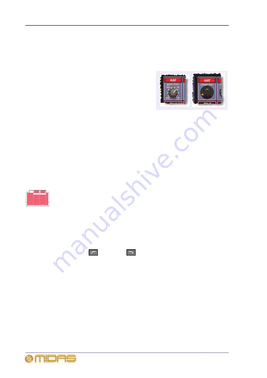
Press the left-right arrow gain swap button
(or click GAIN SWAP) to swap the gain
trim and stage box sections over. The
diagram right shows the two types of gain
that can appear in the input gain/trim
section at the top of each input fast strip.
3
Adjust the gain trim control knob (5dB
steps from -2.5dB to +45dB) to the
required level to suit the Midas pre-amp
characteristic. A suitable level could be one that only just illuminates the yellow
LEDs. Do this for each required channel.
Drive the mic amps for that ‘Midas colouration’; feel free to overdrive if you want.
4
After you have achieved the required gain state, press the left-right arrow gain
swap button (or click GAIN SWAP) to swap the gains back to their default state.
5
Adjust the gain trim control knob to (this time) adjust the console digital trim
(+20dB to -40dB continuous trim) for your preferred gain structure.
6
Set analogue remotes for initial set-up, then adjust digital trim for showtime.
Setting the high and low pass filters
Select high and low pass filters. The high and low pass filters can be switched be on/off
and, when on, each has two settings. The filters are replicated on the GUI, which also
shows the value of the filter in operation.
>> To set both high and low pass filters in
1
In the gain trim section of an input fast strip (see Figure 11 “Gain and filter
sections of the input strips” on page 79), press the quick access button. This
selects the input channel and assigns its configuration processing area to GUI
channel strip, which contains the filters section.
2
In the filters section of the input channel strip, press the filter select button
(high pass
or
low pass
) to switch the filter in.
3
If necessary, press the filter’s SLOPE button to set its slope (dB); its status is
shown on the GUI. For the high pass filter, in = 24dB and out = 12dB, and for the
low pass filter, in = 12dB and out = 6dB.
4
Adjust the high pass/low pass control knob to set the filter frequency (Hz).
The ranges are 10Hz to 400Hz for the high pass filter and 2kHz to 40kHz for the
low pass filter.
Содержание PRO6
Страница 2: ......
Страница 4: ......
Страница 6: ......
Страница 10: ......
Страница 14: ...xvi Precautions PRO6 Live Audio System Owner s Manual...
Страница 24: ...xxvi Contents PRO6 Live Audio System Owner s Manual...
Страница 25: ...PRO6 Live Audio System Owner s Manual Volume 1 Overview...
Страница 26: ......
Страница 30: ...4 Chapter 1 Introduction PRO6 Live Audio System Owner s Manual...
Страница 42: ...16 Chapter 2 PRO6 Live Audio System PRO6 Live Audio System Owner s Manual...
Страница 50: ...24 Chapter 3 About The PRO6 Control Centre PRO6 Live Audio System Owner s Manual...
Страница 51: ...PRO6 Live Audio System Owner s Manual Volume 1 Getting Started...
Страница 52: ......
Страница 59: ...PRO6 Live Audio System Owner s Manual Volume 2 Basic Operation Of The PRO6...
Страница 60: ......
Страница 64: ...38 Chapter 5 Before You Start PRO6 Live Audio System Owner s Manual...
Страница 104: ...78 Chapter 8 Patching PRO6 Live Audio System Owner s Manual...
Страница 131: ...PRO6 Live Audio System Owner s Manual Volume 3 Advanced Operation And Features...
Страница 132: ......
Страница 136: ...110 Chapter 10 Stereo Linking PRO6 Live Audio System Owner s Manual...
Страница 144: ...118 Chapter 11 Panning PRO6 Live Audio System Owner s Manual...
Страница 148: ...122 Chapter 12 Soloing PRO6 Live Audio System Owner s Manual...
Страница 150: ...124 Chapter 13 Muting PRO6 Live Audio System Owner s Manual...
Страница 192: ...166 Chapter 18 Copy And Paste PRO6 Live Audio System Owner s Manual...
Страница 242: ...216 Chapter 24 User Libraries Presets PRO6 Live Audio System Owner s Manual...
Страница 246: ...220 Chapter 25 File Management PRO6 Live Audio System Owner s Manual...
Страница 250: ...224 Chapter 26 Using Other Devices With The PRO6 PRO6 Live Audio System Owner s Manual...
Страница 267: ...PRO6 Live Audio System Owner s Manual Volume 4 Description...
Страница 268: ......
Страница 335: ...PRO6 Live Audio System Owner s Manual Volume 5 Appendices...
Страница 336: ......
Страница 365: ...Audio signal path 339 PRO6 Live Audio System Owner s Manual Audio signal path...
Страница 366: ...340 Appendix C Klark Teknik DN370 GEQ PRO6 Live Audio System Owner s Manual...
Страница 372: ...346 Appendix D Klark Teknik DN780 Reverb PRO6 Live Audio System Owner s Manual...
Страница 376: ...350 Appendix E I O Modules PRO6 Live Audio System Owner s Manual...
Страница 400: ...374 Appendix I Documentation PRO6 Live Audio System Owner s Manual...
Страница 511: ...Return 485 XL8 Live Performance System Owner s Manual Gate Not applicable EQ Not applicable...
Страница 524: ...498 Appendix N Parameters Affected By Copy And Paste XL8 Live Performance System Owner s Manual...
Страница 568: ...542 Appendix O Parameters Affected By Stereo Linking XL8 Live Performance System Owner s Manual...
Страница 612: ...586 Glossary PRO6 Live Audio System Owner s Manual...


