background image

4-47

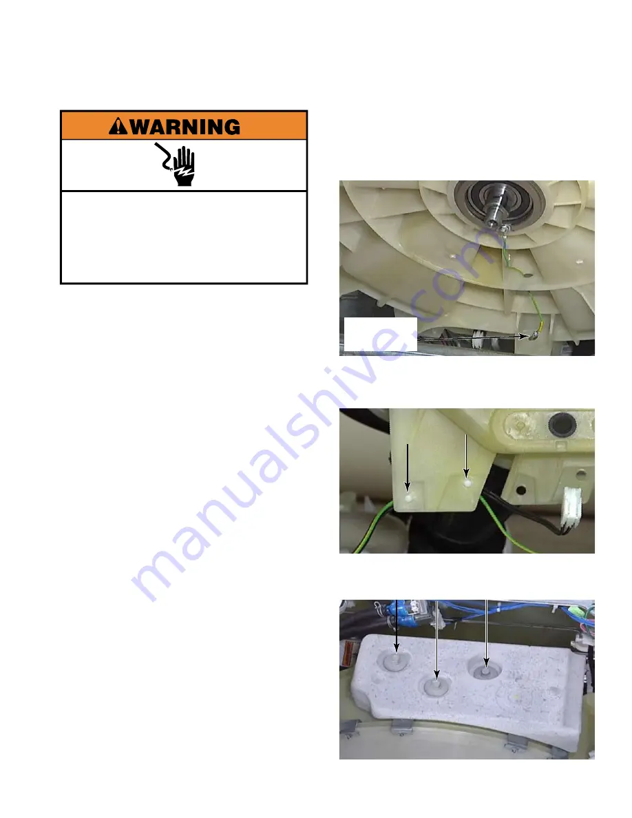
  Disconnect the ground wire to the hub 

at the spade connection about 12 inches 

from the hub. Follow the ground wire from 

the hub to the connector to locate the 

disconnecting point.

  Remove the wire retainers by pressing the 

Christmas tree clips out of the holes in the 

bottom of the outer tub.

  Remove three 1/2” bolts that secure top 

rear weight to outer tub, and remove weight.

12.

13.

14.

Electrical Shock Hazard

Disconnect power before servicing.

Replace all parts and panels before

operating.

Failure to do so can result in death or

electrical shock.

Unplug washer or disconnect power.

Turn off the water supply to the washer.

Remove the chemical dispenser assembly 

(See page 4-14).

Remove the washer front support bracket  

(See page 4-46).

Remove the bellow (See page 4-44).

Disconnect the tub to pump hose from 

pump (See page 4-30).

Remove the rear panel (See page 4-36).

Remove the basket pulley (See page 4-38).

Disconnect the vent tube (See page 4-39).

  Remove the wiring connector from the 

temperature sensor (See page 4-40).

  Remove the motor (See page 4-41).

1.

2.

3.

4.

5.

6.

7.

8.

9.

10.

11.

reMOve TuB anD SPin BaSkeT aSSeMBly

Ground Wire 

Disconnect

Содержание MLE20PDAYW0

Страница 1: ...Maytag Commercial Stacked Washer Dryer Service Manual MLE20PDAYW0 MLG20PDAWW0 MLE20PDAZW0 W10376697 TECHNICAL EDUCATION MODELS MLE20PRAYW0 MLG20PRAWW0 MLE20PRAZW0 ...

Страница 2: ...ed with the washer dryer The Wiring Diagrams used in this Service Manual are typical and should be used for training purposes only Always use the Wiring Diagram supplied with the product when servicing the washer GOALS AND OBJECTIVES The goal of this Service Manual is to provide information that will enable the Commercial Laundry Service Professional to properly diagnose malfunctions and repair th...

Страница 3: ... clearances 2 10 Stacked washer electric dryer electrical requirements 2 11 Dryer venting requirements 2 14 Dryer gas supply requirements 2 18 Gas pipe chart Natural gas 2 20 Washer drain system 2 21 Stacked washer dryer maintenance instructions 2 22 Remove shipping bolts 2 25 Reinstall shipping bolts 2 25 BASIC OPERATION 3 1 Electronic control setup instructions 3 1 General user information 3 2 C...

Страница 4: ...itting 4 18 Remove washer power cord MLE model only 4 19 Remove door lock switch assembly 4 20 Remove door hook 4 22 Remove door and hinge assembly 4 22 Washer door parts and disassembly 4 23 Remove stacked washer dryer base 4 25 Remove washer lower service panel 4 26 Remove drain pump 4 27 Remove drain pump motor 4 29 Remove tub to pump hose 4 30 Remove ground switch 4 31 Remove washer central co...

Страница 5: ...r belt 4 67 Remove dryer drum 4 68 Remove a dryer baffle 4 69 Remove dryer thermistor 4 70 Remove dryer thermal fuse 4 70 Remove dryer blower wheel 4 71 Remove dryer blower housing 4 72 Remove dryer exhaust duct 4 73 Remove dryer motor and speed increaser 4 74 Remove dryer motor bracket 4 76 Remove dryer belt switch 4 77 Remove dryer idler pulley 4 77 Remove drum rear support rollers 4 78 Remove r...

Страница 6: ... cutout electric dryers only 5 16 Centrifugal switch 5 17 Drive motor 5 18 Thermistor 5 20 Thermal fuse 5 21 Transformer 5 22 DIAGNOSIS TROUBLESHOOTING 6 1 Diagnostic mode 6 1 Failure displays 6 2 Dryer diagnostic codes 6 2 Washer diagnostic codes 6 3 Washer quick overview test 6 8 Washer manual overview test 6 9 Diagnostic test quick guide 6 10 Washer help codes 6 11 Dryer help codes 6 11 Help mo...

Страница 7: ...Washer troubleshooting guide 6 18 Dryer troubleshooting guide 6 19 Troubleshooting tests 6 20 Unusual sounds 6 28 Dryer displaying code message 6 29 Troubleshooting dryer results 6 30 Clothes are not drying satisfactorily drying times too long or load is too hot 6 30 Lint on load 6 31 Stains on load or drum 6 31 Loads are wrinkled 6 31 Odors 6 31 WIRING Diagrams 7 1 U S electric 7 1 U S gas 7 2 Ca...

Страница 8: ...nks section to open the attached document This symbol means a video clip is available Click the mouse on the camera icon to view the video To close the movie click the X box at the top corner of the video window System requirements to view the video clips in this manual are Windows 2000 or higher Adobe Acrobat Reader version 6 or higher Windows Media Player for PC and Quicktime Player for Macintos...

Страница 9: ...strap to green ground connection point or unpainted metal in the appliance OR Touch your finger repeatedly to a green ground connection point or unpainted metal in the appliance Before removing the part from its package touch the anti static bag to a green ground connection point or unpainted metal in the appliance Avoid touching electronic parts or terminal contacts handle electronic control asse...

Страница 10: ... X 120V 60Hz Canada G 220 240V 50Hz Export Models COLOr W White enGineerinG CHanGe nuMeriC MODeL nuMBer DeSiGnaTiOnS SeriaL nuMBer DeSiGnaTiOnS SeriaL nuMBer M 1 35 10901 DiViSiOn reSPOnSiBiLiTY M Marion Ohio HL Monterrey MX Year OF PrODuCTiO W 2008 Y 2009 0 2010 1 2011 WeeK OF PrODuCTiOn 35 35th Week in the calendar year ManuFaCTurinG SeQuenCe nuMBer HP AH Automatic Horizontal Axis Washer 22 Comm...

Страница 11: ...1 3 Location of Model Serial Number Label Location of Tech Sheet Parts List Wiring Diagram Service Key Model serial number label and tech sheet location ...

Страница 12: ...es 6 Cycles Product Weight uncrated Card Reader Not Included Product Weight crated 2 mm 730 68 58 cm 3 2 ft Normal 40 RPM 1 4 SPeCiFiCaTiOnS Width Front Load HE W Model Number Model Description Color White Black Accents Stainless Steel Trim Washer Temperature Control NTC Thermister Washer Sensors Suds Sensor NTC Thermistor Water Level Sensor Wash Speed Spin Speeds Max 1000 RPM Medium 850 RPM Low 7...

Страница 13: ...ions made to the commercial appliance 7 The removal and reinstallation of your commercial appliance if it is installed in an inaccessible location or is not installed in accordance with published installation instructions 8 Chemical damage is excluded from all warranty coverage 9 Changes to the building room or location needed in order to make the commercial appliance operate correctly DISCLAIMER ...

Страница 14: ...1 6 NOTES ...

Страница 15: ... adjustable wrench that opens to 1 Flat blade screwdriver Star blade screwdriver T 20 security screwdriver 1 hex head socket or wrench 5 16 socket or wrench Pliers that open to 1 9 16 Level Utility knife 1 4 nut driver Locking pliers Caulk gun and caulk if installing new vent Vent clamps Pipe joint compound suitable for gas type 27 wood block 1 2 and 9 16 open end wrenches Ruler or measuring tape ...

Страница 16: ...ber 285835 Floor drain system Siphon break Part Number 285834 Connector Kit x2 Part Number 285835 Extension Drain Hose Part Number 285863 Water faucet beyond reach of fill hoses 2 longer water fill hoses 6 ft 1 8 m 90 bend hose Part Number 76314 10 ft 3 0 m hose Part Number 350008 Alternate parts Enhance the washer dryer with these premium accessories For more high quality items or to order call 1...

Страница 17: ...s Clearances 7 DIMENSIONS CLEARANCES Front View Side View Back View 1 25 mm 74 1880 mm 51 1295 mm 29 5 751 mm 1 2 27 686 mm 1 25 mm 74 1880 mm Dimensions Clearances Side Clearances Back Top Clearances 0 0 mm 0 0 mm ...

Страница 18: ...electrical outlet located within 6 ft 1 8 m of where the power cord is attached to the back of the washer See Electrical Requirements Hot and cold water faucets located within 4 ft 1 2 m of the hot and cold water fill valves and water pressure of 20 100 psi 137 9 689 6 kPa A level floor with a maximum slope of 1 25 mm under entire washer dryer Installing the washer dryer on soft floor surfaces suc...

Страница 19: ...ly opened Additional spacing should be considered for ease of installation and servicing The doors open more than 180 The washer door is not reversible Additional clearances might be required for wall door and floor moldings Additional spacing of 1 25 mm on all sides of the washer dryer is recommended to reduce noise transfer Companion appliance spacing should also be considered When Installing A ...

Страница 20: ...recommended that a separate circuit serving only this washer dryer be provided This washer dryer is equipped with a power supply cord having a 3 prong grounding plug To minimize the possibility of shock the cord must be plugged into a mating 3 prong grounding type outlet grounded in accordance with local codes and ordinances If a mating outlet is not available it is the personal responsibility and...

Страница 21: ...2 7 Stacked Washer Gas Dryer Grounding ...

Страница 22: ... a qualified person make sure gas pressure does not exceed 14 36 cm water column Examples of a qualified person include licensed heating personnel authorized gas company personnel and authorized service personnel Failure to do so can result in death explosion or fire The design of this washer dryer has been certified by CSA International for use at altitudes up to 10 000 feet 3048 m above sea leve...

Страница 23: ...improves performance and minimizes noise and possible washer walk The washer dryer can be installed in a basement laundry room or recessed area See Drain System Companion appliance location requirements should also be considered IMPORTANT Do not install or store the washer dryer where it will be exposed to the weather Do not store or operate the washer dryer in temperatures at or below 32 F 0 C So...

Страница 24: ...nsidered Recessed Area and Closet Installation Instructions This washer dryer may be installed in a recessed area or closet For recessed area and closet installations minimum clearances can be found on the warning label on the rear of the dryer The installation spacing is in inches and is the minimum allowable Additional spacing should be considered for ease of installation servicing and complianc...

Страница 25: ... If a mating outlet is not available it is the personal responsibility and obligation of the customer to have the properly grounded outlet installed by a qualified electrician If codes permit and a separate ground wire is used it is recommended that a qualified electrician determine that the ground path is adequate Check with a qualified electrician if not sure that the washer is properly grounded...

Страница 26: ...d for 1 new branch circuit installations 2 mobile homes 3 recreational vehicles and 4 areas where local codes prohibit grounding through the neutral conductor n n n Dryer Electrical Requirements It is your responsibility To contact a qualified electrical installer To be sure that the electrical connection is adequate and in conformance with the National Electrical Code ANSI NFPA 70 latest edition ...

Страница 27: ...If using a power supply cord Use a UL listed power supply cord kit marked for use with clothes dryers The kit should contain A UL listed 30 amp power supply cord rated 240 volt minimum The cord should be type SRD or SRDT and be at least 4 ft 1 22 m long The wires that connect to the dryer must end in ring terminals or U shaped spade terminals with upturned ends A UL listed strain relief n n Fire H...

Страница 28: ...ire and be Flexible armored cable or nonmetallic sheathed copper cable with ground wire covered with flexible metallic conduit All current carrying wires must be insulated 10 gauge solid copper wire do not use aluminum At least 5 ft 1 52 m long n n n Fire Hazard Use 10 gauge copper wire Use a UL listed strain relief Disconnect power before making electrical connections Connect neutral wire white o...

Страница 29: ...reduced airflow and poor performance Do not install in enclosed walls ceilings or floors The total length should not exceed 73 4 ft 2 4 m NOTE If using an existing vent system clean lint from entire length of the system and make sure exhaust hood is not plugged with lint Replace plastic or metal foil vents with rigid metal or flexible metal vents Review Vent System Chart and if necessary modify ex...

Страница 30: ...o Of 90 Turns Box and Louvered Hood Angled Hood 0 135 ft 41 2 m 129 ft 39 3 m 1 125 ft 38 1 m 119 ft 36 3 m 2 115 ft 35 1 m 109 ft 33 2 m 3 106 ft 32 3 m 100 ft 30 5 m 4 98 ft 29 9 m 92 ft 28 0 m For vent systems not covered by the vent specification chart see your parts distributor Provision must be made for enough air for combustion and ventilation Check governing codes and ordinances See Recess...

Страница 31: ...t should enter the main vent at an angle pointing in the direction of the airflow Vents entering from the opposite side should be staggered to reduce the exhausted air from interfering with the other vents The maximum angle of each vent entering the main vent should be no more than 30 If An Exhaust Hood Cannot Be Used The outside end of main vent should have a sweep elbow directed downward Minimum...

Страница 32: ...located in same room as dryer It should be in a location that allows ease of opening and closing Do not block access to shut off valve In Canada an individual manual shut off valve must be installed in accordance with the B149 installation codes CAN CGA B149 1 and CAN CGA B149 2 Dryer gas supply requirements Type Of Gas This dryer is equipped for use with natural gas It is design certified by CSA ...

Страница 33: ...line The gas pipe which extends through the lower rear of the dryer is provided with 3 8 10 mm male pipe thread NOTE Do not kink or damage the flexible stainless steel gas line when moving dryer Rigid Pipe Connection The rigid pipe connection requires a combination of pipe fittings to obtain an in line connection to dryer TEFLON is a registered trademark of E I Du Pont De Nemours and Company ...

Страница 34: ...he top of the chart are lengths of pipe from 10 feet up to 200 feet The numbers in the body of the chart are maximum capacities of cubic feet of gas per hour To determine the cubic feet of gas required per hour divide the total BTU input of all the dryers which will be on the line by the average BTU heating value per cubic foot of the gas used Nominal iron pipe size inches Internal diameter inches...

Страница 35: ...ll The top of the standpipe must be at least 30 762 mm high and no higher than 96 2 4 m from the bottom of the washer Floor Laundry Tub Drain System Laundry tub needs a minimum 20 gal 76 L capacity The top of the laundry tub must be at least 30 762 mm above the floor Floor Drain System The floor drain system requires a siphon break that may be purchased separately The siphon break Part Number 2858...

Страница 36: ...the Washer Cleanout cycle first enter Service Mode Then press and hold the lower right QUICK CYCLE button for 2 seconds With the entire display flashing press the center right BRIGHTS button n n 1 2 3 4 Stacked washer dryer maintenance instructions Washer Cleaning The Door Seal Bellow Open the washer door and remove any clothing or items from the washer Inspect inner glass door If debris is presen...

Страница 37: ...ments Wash the parts under running water NOTE Do not wash components in the dishwasher Reinstall the inserts and return the dispenser to the drawer n n n n 1 2 3 4 To exit out of the service mode and activate the clean wash cycle push the BRIGHTS button then turn the key NOTE The door will lock the basket will rotate 1 2 turn then the door will unlock and lock again then the Washer Cleanout Cycle ...

Страница 38: ...area clear and free from items that would obstruct the flow of combustion and ventilation air If Dryer Does Not Operate Check The Following Electrical supply is connected Circuit breaker is not tripped or house fuse is not blown Door is closed Listen closely to hear the door switch activate Cycle selection button has been pushed firmly For gas dryers check that gas supply shut off valves are set i...

Страница 39: ...s If washer must be transported after shipping bolts have been removed at least 2 shipping bolts must be re installed to avoid damage to washer components from the movement of the weights and the tub Unplug washer or disconnect power Turn off the water supply to the washer Remove the back panel from the washer Assemble plastic tub spacers onto shipping bolts Insert each shipping bolt assembly thro...

Страница 40: ...2 26 NOTES ...

Страница 41: ... Enhanced Debit mode J Ed In Enhanced Debit mode the card balance will also display when a debit card is inserted into the reader 1 Door must be closed on the desired washer dryer before cycle selection is made Press the fabric setting button for the washer dryer cycle desired For washer cycles also select the desired wash temperature After the cycle is started the time will display and count down...

Страница 42: ...dryer section and diagnostic codes displayed on the lower portion of the display apply to the washer section Diagnostic codes displayed on both the upper and lower portions of the display pertain to the control system of both the washer and dryer 0 Minutes Showing In Display This indicates the cycle is complete and the washer dryer cannot be operated Coins dropped or debit inputs during this condi...

Страница 43: ... debit card system debit pulses represent the equivalent of one coin coin 1 Warm Start after power failure A few seconds after power is restored if a cycle was in progress at the time of the power failure RESELECT CYCLE will flash in the display indicating the need for a key press to restart washer or dryer Washer Door Lock Prior to beginning a cycle there is a door lock routine of lock unlock rel...

Страница 44: ... selection or deselection 1 2 3 Control set up procedure IMPORTANT Read all instructions before operating PD PR Models Insert service switch key and turn counter clockwise PR Models Once a Generation 2 debit card reader is installed according to the reader manufacturer s instructions the set up modes can be changed by inserting a set up card supplied by the reader manufacturer into the card slot I...

Страница 45: ...by pressing the lower left PERM PRESS button Factory default of 7 quarters 1 75 6 00 PR MODELS ONLY Factory default of 6 00 or 0 quarters Press the lower middle DELICATES AND KNITS button once to advance to next code 6 06 REGULAR CYCLE PRICE DRYER 6 06 Represents the number of quarters coin 1 needed to start the dryer may adjust from 0 39 See VALUE OF COIN 1 Advance from 0 39 by pressing the upper...

Страница 46: ...ME DRYER 7 05 PD MODELS Represents the number of minutes per quarter coin 1 Factory default of 5 minutes per coin Example 6 quarters x 5 minutes 30 minutes By pressing the upper left WHITES COLORS button value adjusts from 1 99 minutes 7 45 PR MODELS Represents the cycle length for free cycles As example 7 45 45 minutes Press the lower middle DELICATES AND KNITS button once to advance to next code...

Страница 47: ...ower middle DELICATES AND KNITS button once to advance to next code CODE EXPLANATION F 00 ENHANCED PRICING OPTION WASHER F 00 Not Selected 00 F CP Cycle Based pricing enabled This option allows configuration of different prices for cold warm and hot water wash cycles F SU Super Cycle pricing enabled This option allows customers to upgrade cycles by depositing extra money Set up codes H and h will ...

Страница 48: ...50 rpm 800 rpm 1000 displays as 999 rpm Step between speeds by pressing the lower left PERM PRESS button Factory default of 800 rpm Press the lower middle DELICATES AND KNITS button once to advance to next code U 00 PENNY INCREMENT OFFSET WASHER U 00 This represents the penny increment price offset used in Generation 2 Enhanced Debit PR models Choose from 0 4 pennies by pressing the lower left PER...

Страница 49: ... in the washer and or the next user adds too much detergent as well Theory of operation The idea behind the development of the Stacked Washer Dryer was to have a product with a small enough footprint that could deliver the same washing and drying capability as well as load size of the freestanding washer and freestanding single dryer in half the area Combining payment systems and operating with a ...

Страница 50: ...ead and then into the drum As the dry heated air circulates in the drum it picks up moisture from the wet clothes The more space around tumbling clothes for dry heated air to come Into contact with fabric the faster clothes will dry igid duct with the dryer for additional information nstructions provided duct Electri Canada 240v 5250 watts 30 amp fuse v 5600 USA 240 or less than 0 water column Cap...

Страница 51: ...motor switch M1 to M2 is closed When WHITES AND COLORS is selected the high heat cycle is activated The high temp cycle uses the circuit that involves the 155 F setting of the exhaust thermistor When the cycle type is selected on PD models the dryer motor circuit is energized The motor has power sent to both the Run and the Start windings When the motor reaches run speed the centrifugal switch sna...

Страница 52: ...ol that senses this and activates or deactivates the relays on the board Whenever a door switch state is sensed as closed the UIC allows the Select Cycle or Reselect Cycle to display on PD or PR models after correct vend price is applied On PR models set up for free vend the display would show Select Cycle after the door switch state is changed and then detected as closed With all pay for use comm...

Страница 53: ...adiant Sensor Contacts Closed The holding coil the booster coil and the ignitor all receive line voltage The holding coil and booster coil open gas valve 1 Gas valve 2 is still closed prohibiting gas to flow to the burner The ignitor operating at line voltage begins to get very hot as the ignitor gets hotter the resistance of the ignitor drops The ignitor glow radiates heat to the radiant sensor a...

Страница 54: ...er drying times for the clothes or cause the dryer to stop before the load is completely dry The screen is probably clogged if lint falls off while the screen is in the dryer Clean the lint screen with a nylon brush every 6 months or more frequently if it becomes clogged due to a residue buildup To Wash Roll lint off the screen with your fingers Wet both sides of lint screen with hot water Wet a n...

Страница 55: ... Unplug dryer Close shutoff valve in gas supply line Disconnect gas supply line pipe and remove fittings attached to dryer pipe Cap the open fuel supply line Make sure leveling legs are secure in dryer base Use masking tape to secure dryer door For direct wired dryers Disconnect power Disconnect wiring Make sure leveling legs are secure in dryer base Use masking tape to secure dryer door 1 2 3 1 2...

Страница 56: ...3 16 NOTES ...

Страница 57: ...tall it by clipping it onto the crossbar in the openings 5 6 7 COMPONENT ACCESS Pull the chemical dispenser drawer out as far as it will go Press the release tab down in the top left rear corner of the drawer using a small flat blade screwdriver Pull the dispenser drawer out of the washer The detergent cup insert can be removed for cleaning by lifting it out of the detergent drawer 1 2 3 4 Remove ...

Страница 58: ...urity screws The chemical dispenser drawer facia is secured with sheet metal screws The User Interface facia is secured with machine screws Make sure not to interchange these screws The front of the chemical dispenser drawer is called the handle and it can come off if pulled too hard Reinstall the handle by straightening the tabs hook the top three tabs onto the drawer and rotate the front down to...

Страница 59: ...ion Disconnect the wire connectors from the control board Press the locking tab and disconnect the service switch wire connector Lift the control panel to release the hook from the hoop on the control panel bracket Remove the control panel and place it on a covered work surface 4 5 6 7 8 Remove control panel Electrical Shock Hazard Disconnect power before servicing Replace all parts and panels bef...

Страница 60: ...elease two tabs and open the small cover to access this sub control board TECH TIP This sub control board maintains the factory installed software for the stacked washer dryer If replacing a failed main control board that did not damage the sub control the sub control should be saved as a viable repair part as this sub control is not available as a separate service part Turn the assembly over to v...

Страница 61: ...racket Mount the card reader and bezel into the bracket NOTE The card reader cable is factory supplied and needs to be connected to AA3 on the control board The connection AA1 on the control board is for the service and coin vault switches and is present on the control board of PR PN models as well as the PD models The PR PN models will have a jumper across the coin vault connections of this conne...

Страница 62: ...ath or electrical shock Open the control panel See page 4 3 Remove four 1 4 hex head screws that secure the coin drop mounting bracket to the control panel bracket Press the locking tab and disconnect coin drop wire connector from the control board Untwist the wire clips inside the control panel to release the wires Pull the coin drop and bracket out while pulling the wire through the hole in the ...

Страница 63: ...nting bracket with bolts attached from the top of the coin vault 1 2 3 4 Release the coin vault switch wires from the clip on the control panel bracket and slide the coin vault out of its support bracket Remove two wire connectors from the back of the coin vault switch To remove the coin vault switch reach into the coin vault compartment and push the switch in as far as possible Slide the switch u...

Страница 64: ...l assembly 1 2 3 4 Remove the lock from the front of the control panel cover TECH TIP When reassembling the service switch assembly place metal switch bracket against the control panel and then the plastic bracket on top of the metal bracket Remove the two wire connectors from the switch by pulling them off the spade connectors Remove two 1 star head screws that secure the switch to the bracket an...

Страница 65: ...e the keypad assembly from the front of the control panel cover The keypad assembly consists of a back plastic plate with an elongated peg and a round peg to position the membrane switch and 9 push button plate on The front plate snaps into clips around the edge of the back plate which encloses and secures the push button plate and membrane switch in position 4 5 6 7 Remove keypad assembly Electri...

Страница 66: ... plug 1 2 3 4 Push the wires through the hole of the bracket and remove the control panel bracket The chemical dispenser adapter has clips on the back side of the control panel bracket that can be released once the bracket is removed 5 6 Remove control panel bracket Electrical Shock Hazard Disconnect power before servicing Replace all parts and panels before operating Failure to do so can result i...

Страница 67: ...yer base These strips are each mounted to the washer with two 1 4 hex head screws There is a small plastic clip in a slot on the top of the front rail that supports the front edge of the dryer 4 5 6 7 Remove dryer from stack Electrical Shock Hazard Disconnect power before servicing Replace all parts and panels before operating Failure to do so can result in death or electrical shock excessive Weig...

Страница 68: ...sconnect power Turn off the water supply to the washer Remove the washer hoses from the hot and cold water inlet valves Remove dryer from stack See page 4 11 Lift the locking tabs and disconnect the wire connectors to the water inlet valves The blue connector is for the hot water valve 1 the white connector is for bottom cold water valve 3 and the grey connector is for top cold water valve 2 Loose...

Страница 69: ...iver Clean the filter and reinstall 7 8 Locking Tab Unplug washer or disconnect power Turn off the water supply to the washer Remove the washer hoses from the hot and cold water inlet valves Remove the rear panel See page 4 36 Remove the T 20 screw on the back of the washer that secures each water inlet valve From the back reach inside the washer and twist the valve body to align the locking tabs ...

Страница 70: ...supply to the washer Remove dryer from stack See page 4 11 Remove the hoses to the water inlet valves from the back of the chemical dispenser Make note which hose is connected to which inlet There is a water metering insert in the end of this hose Remove it if necessary by pulling it out of the end of the hose Remove three T 20 screws from the washer front support bracket that secure the top and f...

Страница 71: ...ispenser cover and one on the back that secure the top to the base of the dispenser Remove the top to access the water inlet holes in order to clean any mineral or chemical build up which could slow the incoming water 10 Arrow On Flanged End Line On Chemical Dispenser Arrow On Tube Markings shown are for illustration only and are not present on production models Detergent Fabric Softener Bleach Up...

Страница 72: ...0 degrees and pull the rectangular tab out of the slot in the top of the washer side panel Disconnect the air hose on the bottom of the pressure switch there is no clamp just a pressure fit NOTE Hose should be snug to avoid air leaks check for loose or cracked hose end TECH TIP Pressure switch may be removed from the rear of the washer without removing the dryer Remove the washer rear panel reach ...

Страница 73: ...k wires Pull the L1 and neutral wire connectors off their spade terminals NOTE Problems can occur with this washer if the AC power is connected with reverse polarity When properly installed the neutral wire connector should be toward the front of the washer as viewed from the RFI filter installed orientation To test for proper polarity power must be reconnected to the washer test between the neutr...

Страница 74: ...n hose at the back corner of the washer NOTE Each washer comes from the factory with a U Bend fixture to be used on the drain hose end that fits into the stand pipe or over the sink edge The U Bend needs to be fitted to the drain hose at the very end with no more than 2 inches of the end of the drain hose extending past the end of the U Bend Secure excess drain hose to plumbing or another structur...

Страница 75: ...gh to access the power supply cord on the rear panel 1 2 3 4 5 6 Electrical Shock Hazard Disconnect power before servicing Replace all parts and panels before operating Failure to do so can result in death or electrical shock Remove washer power cord MLE model only Remove the 1 4 hex head screw that secures the power supply cord strain relief to the rear panel of the washer Push the wire connector...

Страница 76: ...connect power before servicing Replace all parts and panels before operating Failure to do so can result in death or electrical shock Unplug washer or disconnect power Turn off the water supply to the washer Open the washer door Remove two T 20 screws that secure the door lock assembly to the front panel of the washer NOTE These screws are different than other screws on the washer and need to be r...

Страница 77: ...xtend completely 7 8 Manual Release Tab Wax Motor Wax Motor Connector Door Closed Switch Door Locked Switch Door Lock Solenoids TECH TIP If the latch has been tripped with the door open by something being poked into the latch it must be unlatched before the door will be able to be closed again There are two ways this can be done Remove the door lock assembly and turn it over to view the back of th...

Страница 78: ...h helps move clothes to the back of the washer during the wash tumble sequence 1 2 3 n Remove door and hinge assembly Two 1 4 Hex Head Screws Remove door hook Open the washer door Remove two T 20 screws that secure the hook to the door Press the locking tab and rotate the hook up and out of the slots in the door REASSEMBLY NOTE When reinstalling the door hook do not tighten the hook completely The...

Страница 79: ...lacing the hinge Use a small flat blade screwdriver to release the clips around the edge of the outer door trim to start separating it from the inner door 1 2 3 4 Finish removing the outer door trim by hand The door handle can now be removed from the slots that are used to locate it on the outer trim The outer door lens can then be lifted off the front of the door assembly NOTE The lens and the ou...

Страница 80: ... with machine screws The door halves are secured with screws for plastic These screws must not be interchanged To remove the bowl remove the hinge and remove three T 20 screws from each of the two brackets secured to the inner door panel These screws also have threads for plastic but are shorter than the screws that secure the door halves together 8 9 Support the inner door trim to avoid having it...

Страница 81: ...washer dryer on its back If the shipping bolts have been removed be aware that the tub assembly will be loose and will move toward the back when the washer is tipped backwards stretching the boot Loosen the two top 5 16 hex head screws that secure the base to the bottom of the washer Remove two bottom 5 16 hex head screws Lift the base up off the top two screws to remove it Remove the legs by unsc...

Страница 82: ... the panel down and toward the washer to pop it into place Install the remaining 2 screws and secure all screws tightly 1 2 3 4 Electrical Shock Hazard Disconnect power before servicing Replace all parts and panels before operating Failure to do so can result in death or electrical shock Remove washer lower service panel Components located behind the washer lower service panel are Drain pump Centr...

Страница 83: ...r or disconnect power Turn off the water supply to the washer Remove the washer lower service panel See page 4 26 Place a towel or shallow pan below the pump to catch any water that may be left in the system TECH TIP If a pan or towel is not accessible remove the paperwork from inside the washer lower service panel Place the straight edge of the panel against the washer base under the pump to catc...

Страница 84: ...tch on the pump that it aligns with NOTE If squeeze clamp does not seem to hold hose on the pump sufficiently it can be replaced with a standard worm gear clamp 7 8 9 10 Disconnect the tub to pump hose by squeezing the ears of the clamp and pulling the hose off NOTE When reinstalling the tub to pump hose align the arrow on the pump with the tab on the hose Remove the pump from the washer NOTE Ther...

Страница 85: ... be a locking tab that is located near the top of the pump Use a flat blade screwdriver to press the tab in toward the motor while twisting the motor off the pump The pump assembly can be taken apart for cleaning Use a flat blade screwdriver to lift the pump rotor out of the pump The rotor has a magnetic attraction to the motor NOTE When reassembling the pump make sure the seal is clean of foreign...

Страница 86: ...Remove the hose clamp from the tub and remove the tub to pump hose 6 7 8 Electrical Shock Hazard Disconnect power before servicing Replace all parts and panels before operating Failure to do so can result in death or electrical shock Unplug washer or disconnect power Turn off the water supply to the washer Remove the washer lower service panel See page 4 26 Place a towel or shallow pan below the p...

Страница 87: ...lign the air hose fitting with the opening at the right side of the tub opening flange There is also an alignment arrow on the pump that should be aligned with the notch on the hose n n Electrical Shock Hazard Disconnect power before servicing Replace all parts and panels before operating Failure to do so can result in death or electrical shock Remove ground switch Front Ground Switch Rear Ground ...

Страница 88: ...river to press in on the 2 locking tabs in the bottom slots to release the switch Slide the switch up and pull it out of the slots to remove it Release the 2 wires from the clips on each side of the ground switch and pull the connectors off the spade terminals 4 5 6 Locking Tabs Wire Connectors Wire Clips Ground Switch Switch Holder Locking Tabs Ground Switch ...

Страница 89: ...s the front of the washer to release tabs from keyhole slots in the bracket in the base of the washer and remove it Release the wire clips by pressing down and sliding the tab of the clip out from under the hook Use a small flat blade screwdriver to press the locking tab that secures each wire connector to the CCU and remove the connectors 5 6 7 8 Remove washer central control unit CCU Electrical ...

Страница 90: ... BK Stripe DL3 Door Lock 3 BK Wires GN Stripe 4 BU Wires BU Stripe TH2 Temp Sensor 2 BK Wires No Stripe Mi3 3 BU Wires MS2 Drive Motor WH Stripe DLS2 Door Lock Switch iF2 Line Filter 2 Pink Wires Board Edge Connectors Connector Locking Tabs CENTRAL CONTROL UNIT not used MCu interface He2 Wax Motor not used user interface MS2 MCU Drive Motor Power 3 BK Wires GN Stripe Di6 Hot Water inlet 1 vCH7 Col...

Страница 91: ...ties will be provided with a replacement MCU but not new base clips It is necessary to replace all cut broken or damaged wire ties 5 6 7 8 Unplug washer or disconnect power Turn off the water supply to the washer Remove the washer lower service panel See page 4 26 Open the door of the MCU and disconnect the four wire connectors from the MCU 1 2 3 4 Electrical Shock Hazard Disconnect power before s...

Страница 92: ... panels before operating Failure to do so can result in death or electrical shock Unplug washer or disconnect power Turn off the water supply to the washer If installed remove 4 plastic shipping bolt hole covers by lifting the rounded end to unhook the locking tab from the slot in the chassis and slide cover toward the nearest side panel to release and remove covers Remove the 14 hex head screws t...

Страница 93: ...OTE Both rear braces have been removed for visual clarity they do not need to be removed to service the belt It is not recommended to remove the washer rear supports while the dryer is still in place above the washer Damage to the washer cabinet or instability of the stacked washer dryer may occur if one or both washer rear braces are removed 1 2 3 4 Remove washer drive belt The drive belt is a ri...

Страница 94: ...d pulleys can cause the belt to ride off or get shredded by the motor An excessively warped pulley can cause UNBALANCE to illuminate on the UIC display at the end of a cycle An excessively warped pulley should be replaced 1 2 3 Remove basket pulley Block the pulley to the rear of the tub to keep the spin basket from moving Remove the 15 16 nut securing the pulley to the spin basket Pull the pulley...

Страница 95: ...el See page 4 36 Remove the clamp that secures the vent tube to the back of the tub and disconnect the tube from the tub 1 2 3 4 Remove vent tube Vent Tube Clamp Vent Tube To remove the vent tube from the washer reach inside from the back of the washer and lift the vent tube to release 2 tabs from slots in the top back brace NOTE Inside there is a one way flapper valve that will not allow suds to ...

Страница 96: ...from the sensor Pull the temperature sensor out of the tub with a slight twisting motion 1 2 3 4 5 Remove temperature sensor Remove and replace the grommet only if necessary When installing a grommet the flanges of the grommet must seal inside and outside of the hole in the outer tub It is easier to reinstall the grommet once it is separated from the sensor It may help to wet the temperature senso...

Страница 97: ...f the spade connector Squeeze the Christmas tree clip to remove the wire tie connected to the motor Press the locking tabs and disconnect the motor wire harness plug 1 2 3 4 5 6 7 Remove motor Remove the 1 2 bolt securing the motor to the tub Rotate the motor down and slide the mounting posts out of the holes of the tub by rocking the motor up and down while pulling it away from the washer NOTE Wh...

Страница 98: ...ed up out of the washer 7 8 Unplug washer or disconnect power Turn off the water supply to the washer Remove the washer lower service panel See page 4 26 or Remove the rear panel See page 4 36 Use a small flat blade screwdriver to lift one of the locking tabs Turn the fitting of the damper slightly to hold that locking tab unlocked Reach around to the other side and release the other locking tab T...

Страница 99: ...nnect power before servicing Replace all parts and panels before operating Failure to do so can result in death or electrical shock Unplug washer or disconnect power Turn off the water supply to the washer Remove the door lock assembly See page 4 20 Remove the control panel See page 4 3 Remove the washer lower service panel See page 4 26 Remove two 1 4 hex head screws that were hidden by the washe...

Страница 100: ... front support bracket and remove the transformer 1 2 3 4 5 6 Electrical Shock Hazard Disconnect power before servicing Replace all parts and panels before operating Failure to do so can result in death or electrical shock Remove UIC transformer Electrical Shock Hazard Disconnect power before servicing Replace all parts and panels before operating Failure to do so can result in death or electrical...

Страница 101: ...weights will make it much easier to reinstall the bellow If there is a complaint that water rolls out the door when the clothes are removed from the washer adjust the front leveling legs slightly lower to raise the front of the washer up slightly and allow pooled water to flow back into the washer If reinstalling the tub into the washer reinstalling the bellow on the outer tub is done before reins...

Страница 102: ...er supply to the washer Remove dryer from stack See page 4 11 Remove the UIC transformer See page 4 44 Remove the two 1 4 hex head screws that secure the plastic strips with locator pegs on the top edge of each side panel Remove the front clip in a slot on the top of the front support bracket 1 2 3 4 5 6 Remove washer front support bracket Electrical Shock Hazard Disconnect power before servicing ...

Страница 103: ...parts and panels before operating Failure to do so can result in death or electrical shock Unplug washer or disconnect power Turn off the water supply to the washer Remove the chemical dispenser assembly See page 4 14 Remove the washer front support bracket See page 4 46 Remove the bellow See page 4 44 Disconnect the tub to pump hose from pump See page 4 30 Remove the rear panel See page 4 36 Remo...

Страница 104: ... 16 17 18 Lift tub straight up to separate the air gap dampers and move it forward out of cabinet NOTE To avoid damage to components in the cabinet base or on the outer tub do not let the tub drop free inside the cabinet If replacing the tub remove the flat nuts that secure the weights to the tub by prying them out of their slots with a flat blade screwdriver Flat nuts may not be supplied with a r...

Страница 105: ...When a new tub is installed use the extra clips supplied with replacement tub 27 28 29 30 Mark any position on the outer tub that does not have a clamp Remove the tub clamps by prying them off with a flat blade screwdriver Press the tab on 2 of the 3 guides around the edge of the tub to release the tub halves These guides will assist in re aligning the tub halves during reassembly Lift rear half o...

Страница 106: ... Pry 2 metal tabs up with a flat blade screwdriver Slide the baffle to release the tabs from the slots in the spin basket and remove it NOTE It is not necessary to remove the spin basket from the tub when replacing a broken baffle Just break off the old baffle and remove all the broken parts Make sure the pry tabs are lowered toward the center of the spin basket Slide the new baffle into the slots...

Страница 107: ... to replace the side panels or the base of the washer separately however the washer cabinet assembly is available for replacement and contains the base and both side panels Washer side panels and base Electrical Shock Hazard Disconnect power before servicing Replace all parts and panels before operating Failure to do so can result in death or electrical shock ...

Страница 108: ...sole are just long enough to allow the cover to rotate up onto the top of the dryer If the wires are too tight and the panel cannot lift onto the top of the dryer disconnect the tight wires from the CCU to avoid damaging the connectors on the CCU Press the locking tabs and disconnect the wire connectors from the control board 3 Remove dryer console cover Electrical Shock Hazard Disconnect power be...

Страница 109: ...4 wire connectors by depressing the locking tabs and pulling the connectors off the control Disconnect K2 Power Relay wire connector by pulling the connector off the control NOTE Use an anti static wrist strap whenever handling electronic control boards or use other precautions to avoid ESD damage to the circuitry 1 2 3 4 Remove dryer control board CCU Press two locking tabs just enough to release...

Страница 110: ...14 P2 3 1 1 6 P4 1 1 8 3 P5 P3 1 P13 1 X v e R X X X X X X N P x x D D D Y e d o C e t a D X X X X X X X O O C N I E D A M N O Black COM Red Heater Relay 1 Motor Relay Tan Black White White Green Yellow Open Lt Blue Black Red White Open Red White Yellow Red Orange Gas Open Elec K2 ...

Страница 111: ...e the second screw down from the top of the door hinge NOTE The hole for this screw is snowman shaped which will allow the screw to pass through it when lifting the door off the dryer Remove the other three star head screws that secure door hinge to dryer front panel NOTE These screws are tapered and serrated The serrated head helps keep the screws tight without a lock washer 1 2 3 4 5 Grasp the d...

Страница 112: ...emove the hinge screw hole cover by gently prying two plastic pins out of the holes 1 2 3 4 5 Reverse a dryer door Install the hinge screw hole cover on the opposite side of the door opening Align the two pins on the back of the cover with the two middle holes for the door hinge Press pins into holes as far as they will go Separate door halves by removing six star head screws from the inside door ...

Страница 113: ... the cover with the two holes for the door hinge screws Press the pins into the holes as far as they will go 11 12 13 Rotate the outer door 180 degrees Place the inner door into the outer door with the hinge on the opposite side of the handle Place inner door into outer door with hinge opposite the handle side Reinstall the six star head screws in the door The longest screw goes in the hole at the...

Страница 114: ...r and press in on the plastic tab on the inside of the door handle Remove the handle from the door 1 2 3 Separate door halves See page 4 56 Remove door handle See left column on this page Rotate inner lens slightly to release the tabs that secure it to the front door half Lift the lens out of the door trim 1 2 3 Remove dryer inner door lens 3 Star Head Screws ...

Страница 115: ...crew that secures drum light lens to the rear bulkhead and remove the lens 1 2 Remove dryer drum light lens Lens Screw Drum Light Lens NOTE There is no light socket on a commercial dryer nor is there capability of adding a light on commercial dryers The lens is maintained as a safety device Behind the light lens is a bracket with a mesh screen This assembly needs to be maintained as it came from t...

Страница 116: ...ch wire from the clip on the lint filter housing Squeeze the Christmas tree clip on the back side of the housing to release the wire harness clip with wire harness attached Remove two 1 4 hex head screws that secure the bottom of front panel to dryer These screws were hidden behind the control panel Remove two 1 4 hex head screws that secure the top of the front panel to the dryer These screws wer...

Страница 117: ...g are brass and the others are not they must be replaced in the same location they are removed from Pull the lint filter housing away from dryer TECH TIP Excess blower vibration may be reduced by loosening the top left screw in the lint filter housing up to two full turns Make sure the foam insulation blocks any gaps Add more foam insulation or aluminum duct tape to seal up any gaps that are creat...

Страница 118: ...elease the wire from the front right side Lift the left side of the front bulkhead so top screw can pass through the snowman hole Lift the drum to release the two rollers attached to the inside of the front bulkhead Remove the front bulkhead Components located on the inside of the front bulkhead are Outlet grill Lint filter door Two support rollers 5 6 7 8 9 n n n Remove dryer front bulkhead Elect...

Страница 119: ...the other two The outer two screws are large pan head screws longer than any other star head screws in the dryer 1 2 Remove dryer outlet grill Lift outlet grill off front bulkhead Separate the two halves of the outlet grill by pulling them apart The lint filter door has a spring on one end of the door that keeps it closed This keeps item from being drawn down into the blower if the dryer is operat...

Страница 120: ...y in position while running 1 2 3 Remove dryer front support rollers and shafts NOTE DO NOT lubricate this wheel or shaft Lubrication attracts lint and dust which will cause premature wear of the support bearing Clean shaft with fine steel wool to eliminate squeaks or replace worn rollers Support roller shafts are secured to the front bulkhead with 9 16 nuts and a washer The washer is installed on...

Страница 121: ...op from the dryer 2 3 Two 1 4 Hex Head Screws Remove two 1 4 hex head screws from the back edge of the top panel 1 Remove dryer top panel Electrical Shock Hazard Disconnect power before servicing Replace all parts and panels before operating Failure to do so can result in death or electrical shock Top Panel Front Tab Front Channel Slot ...

Страница 122: ...x head screw that secures the top bracket to the console bracket Squeeze the Christmas tree clip to remove the wire tie from the console bracket Pull the wires through the hole and remove the bracket 4 5 6 7 Remove dryer console bracket Electrical Shock Hazard Disconnect power before servicing Replace all parts and panels before operating Failure to do so can result in death or electrical shock 1 ...

Страница 123: ...on on the belt Remove the belt from the idler pulley and then remove it from the motor pulley Remove the belt from the dryer NOTE The belt can be reinstalled without removing the drum from the dryer NOTE The belt is a multi ribbed belt When reinstalling the belt make sure the ribs of the belt are facing the drum 1 2 3 4 Remove dryer belt Electrical Shock Hazard Disconnect power before servicing Re...

Страница 124: ...Install dryer drum with the drum clip plug or hole closer to the rear bulkhead of the dryer This is opposite the orientation of the drum in the dryer that matches a top load washer This orientation will allow for quieter operation because the drum supports roll in this direction without a thump as they roll from the higher side to the lower side of the welded seam of the drum To remove a drum clip...

Страница 125: ...oid screws becoming loose from vibration 1 2 Three 1 4 Hex Head Screws Electrical Shock Hazard Disconnect power before servicing Replace all parts and panels before operating Failure to do so can result in death or electrical shock Remove a dryer baffle Open dryer door and hold baffle with one hand while removing the third screw Remove baffle from dryer and replace if necessary 3 4 Baffle ...

Страница 126: ...termine the operating temperature of the dryer based on the resistance being read from the thermistor This resistor has a plastic cone molded over it and the thermistor needs to be removed periodically to clean built up lint from this cone 1 2 3 Remove dryer thermistor Electrical Shock Hazard Disconnect power before servicing Replace all parts and panels before operating Failure to do so can resul...

Страница 127: ...e operating Failure to do so can result in death or electrical shock Remove dryer blower wheel To remove blower wheel when speed increaser belt is broken slipping or missing a thin 7 16 open end wrench WIll be needed to secure speed increaser shaft on its flat spot in lieu of securing the motor pulley TECH TIP When removing blower wheel move 1 2 extension bar in a quick jerking motion rather than ...

Страница 128: ...ire connectors from thermistor and thermal fuse See page 4 70 Remove the short 1 4 hex head screw that secures blower housing to the exhaust duct 1 2 3 Electrical Shock Hazard Disconnect power before servicing Replace all parts and panels before operating Failure to do so can result in death or electrical shock Three 1 4 Hex Head Screws 1 4 Hex Head Screw Four Wire Connectors ...

Страница 129: ...IP When reinstalling exhaust duct or for new dryer installations make sure the anti vibration ring for the exhaust duct is installed in the hole in the back panel of dryer This ring cannot be installed or removed with the exhaust duct in place Remove dryer exhaust duct Electrical Shock Hazard Disconnect power before servicing Replace all parts and panels before operating Failure to do so can resul...

Страница 130: ...t to remove and keep the speed increaser assembly for future repair needs This could save the expense of replacing another motor if a speed increaser fails 4 5 6 Remove dryer drum See page 4 68 Remove blower wheel See page 4 71 To remove motor bracket clips place a 5 16 nut driver over the upward pointing end tip of the mounting clip Press the tool handle down and toward the motor until clip pops ...

Страница 131: ... and out to re align the bars and springs to allow free movement of the switch To remove the speed increaser remove the belt from the speed increaser Remove the two 5 16 hex head screws that secure the speed increaser to the front of the motor TECH TIP If the motor pulley and the speed increaser pulley do not line up properly the small belt may ride off the pulley and may become damaged and need r...

Страница 132: ...to base of dryer Lift bracket to remove two tabs that pass through dryer base and remove bracket from dryer 1 2 3 Remove dryer motor bracket Two 1 4 Hex Head Screws Two Tabs TECH TIP To reduce excess vibration transferred from the motor bracket to the cabinet place anti vibration pads if they are missing under the motor bracket Install two pads if possible or if only one is available then center i...

Страница 133: ...er 1 2 3 4 Remove dryer drum See page 4 68 Remove two star head screws from back of motor bracket Remove two wire connectors and remove switch 1 2 3 Remove dryer belt switch Remove dryer idler pulley Two Wire Connectors Two Star Head Screws Electrical Shock Hazard Disconnect power before servicing Replace all parts and panels before operating Failure to do so can result in death or electrical shoc...

Страница 134: ...wer before servicing Replace all parts and panels before operating Failure to do so can result in death or electrical shock Two rear support rollers Remove dryer drum See page 4 68 Remove the two rear support rollers See page 4 78 Use an adjustable wrench between the rear bulkhead and the back panel to remove the 9 16 nut on each shaft NOTE To support the roller shaft while trying to remove the 9 ...

Страница 135: ...res grounding cable to rear panel Remove two star pan head screws that secure the terminal block to the rear panel 1 2 3 4 5 Remove rear panel Remove ten 1 4 hex head screws that secure the rear panel to the dryer Peel end of insulation strip off of upper edge of rear panel leaving it attached to upper edge of side panel so that it does not tear when removing rear panel Pull rear panel straight aw...

Страница 136: ...servicing Replace all parts and panels before operating Failure to do so can result in death or electrical shock Remove dryer side panel left side shown Two 1 4 Hex Head Screw 1 4 Hex Head Screw Support side panel and lift rear bulkhead and move it forward to release hook from the back edge of the side panel Lay side panel down while continuing to support rear bulkhead To completely remove side pa...

Страница 137: ...rd Disconnect power before servicing Replace all parts and panels before operating Failure to do so can result in death or electrical shock Remove dryer drum See page 4 68 Remove dryer side panels See page 4 80 Support rear bulkhead when removing side panels Use a pair of pliers to squeeze two Christmas tree clips to release wire ties holding wiring harness to rear bulkhead 1 2 3 4 Remove rear bul...

Страница 138: ...wire connectors Remove two 1 4 hex head screws and remove high temp thermostat NOTE The high temp thermostat and high temp cutout should be ordered and replaced as a set The high temp thermostat is resettable and cycles to keep the temperature from getting too hot in the burner 1 2 3 Remove high temp thermostat Two 1 4 Hex Head Screws Electrical Shock Hazard Disconnect power before servicing Repla...

Страница 139: ... control panel bracket See page 4 10 Disconnect wire connector to ignitor Hold on to bracket and remove the 5 16 hex head screw to remove bracket and ignitor Remove ignitor from bracket by removing the 5 16 hex head screw NOTE Do not touch the dark ignitor end skin oil will make a hot spot on the ignitor causing it to fail prematurely NOTE Take care not to bump or tap the ignitor It is extremely b...

Страница 140: ...l panel bracket See page 4 10 Remove two 1 4 hex head screws that secure the brace to the bottom of the dryer Lift brace out of dryer Use a 1 25 mm open end wrench to remove gas line from valve Remove two 1 4 hex head screws under the bracket that secure the gas valve bracket and remove it from dryer 1 2 3 4 Remove gas burner assembly Two Star Head Screws Two 1 4 Hex Head Screws Gas Line Electrica...

Страница 141: ...the orifice as it can block the gas flow and it is not needed TECH TIP When replacing a gas valve assembly it is always prudent to remove the orifice from the original gas valve and install it on the new valve This helps avoid having the wrong size orifice on the dryer after a gas valve replacement NOTE All replacement gas valves for this dryer come set for natural gas use When working on a dryer ...

Страница 142: ...ve electric heating element Lift bracket and heater assembly to remove the bottom edge of the assembly and press down to release the tab from inside the heat plenum at the back of the dryer Remove assembly from the dryer 4 5 Wire Connectors Positioning Tab Electrical Shock Hazard Disconnect power before servicing Replace all parts and panels before operating Failure to do so can result in death or...

Страница 143: ...k Hazard Disconnect power before servicing Replace all parts and panels before operating Failure to do so can result in death or electrical shock Mounting Bracket Tab 1 4 Hex Head Screw NOTE Heater element assemblies have a serviceable electric coil element Since the element is serviceable remove the heater coil from the housing using one pair of pliers to hold the housing and another pair of plie...

Страница 144: ...4 88 NOTES ...

Страница 145: ...d reconnecting wires will be necessary throughout test procedures All tests checks should be made with a VOM or DVM having a sensitivity of 20 000 ohms per volt DC or greater Check all connections before replacing components looking for broken or loose wires failed terminals or wires not pressed into connectors far enough Resistance checks must be made with power cord unplugged from the outlet and...

Страница 146: ...asher the next switch to close is Suds Level and continuity is read between terminals 11 14 The next switch to close is the Wash Level read at terminals 21 24 Finally if water were to rise high enough the Overflow Switch would close between terminals 21 26 1 2 3 4 To check the pressure switch at the CCU perform the following steps with no water in the washer Unplug washer or disconnect power Disco...

Страница 147: ...tors from the RFI line filter Set the ohmmeter to the R X 1 scale Touch the ohmmeter test leads to the following connector pins shown above The meter should indicate 0 ohms for each measurement Pins A and B Pins C and D 1 2 3 4 To check the RFI line filter at the CCU perform the following steps Unplug washer or disconnect power Disconnect the RFI line filter connector IF2 See page 4 34 from the CC...

Страница 148: ...oid 1 3 60 ohms 1 2 3 4 Disconnect the door switch connector See page 4 34 from the CCU To test the door switch touch the ohmmeter test leads to pins 3 and 1 at DS2 The meter should indicate as follows Door closed closed circuit 0 Ω Door open open circuit infinite Ω To test the Wax Motor perform the following steps 1 Unplug washer or disconnect power 2 Remove the latch assembly 3 Disconnect the co...

Страница 149: ...t power Disconnect the wire connector from the drain pump Set the ohmmeter to the R X 1 scale Touch the ohmmeter test leads to the drain pump terminals The meter should indicate approximately 12 3 ohms 1 2 3 4 To check the drain pump at the CCU perform the following steps Unplug washer or disconnect power Disconnect the drain pump connector DP2 See page 4 34 from the CCU Set the ohmmeter to the R ...

Страница 150: ...temperature sensor touch the ohmmeter test leads to the sensor terminals The meter should indicate as shown in the chart below Temperature Result 32 F 0 C 35 9k Ω 86 F 30 C 9 7k Ω 104 F 40 C 6 6k Ω 122 F 50 C 4 6k Ω 140 F 60 C 3 2k Ω 158 F 70 C 2 3k Ω 203 F 95 C 1k Ω 1 2 3 4 To check the temperature sensor at the CCU perform the following steps Unplug washer or disconnect power Disconnect the temp...

Страница 151: ...st leads to the following motor pins For each measurement the meter should indicate approximately 6 Ω Pins 1 and 2 Pins 2 and 3 Pins 1 and 3 1 2 3 4 Ground switch See page 4 31 for the procedure for accessing a ground switch Unplug washer or disconnect power Disconnect the wire connectors from either of the ground switch terminals Set the ohmmeter to the R X 1 scale Touch the ohmmeter test leads t...

Страница 152: ...Failure to do so can result in death or electrical shock See page 4 9 for the procedure for accessing the keypad assembly Unplug washer or disconnect power Set the ohmmeter to the R X 1 scale Set digital ohmmeters to lowest scale Touch the ohmmeter test leads to the contacts listed Press the button listed for each pair of contacts The meter should indicate continuity 0 Ω If the meter indicates an ...

Страница 153: ...ding the coin acceptor plates apart This allows the coin to fall and roll into the coin return bail area The face plate has a coin bail arched area for the coin which is located at the base of the coin return slot The face plate can be removed from the coin acceptor by removing the two screws from the back side of the face plate The coin sensor is mounted to a bar located at the back of the coin a...

Страница 154: ...r test leads to the contacts listed below The meter should indicate as shown in the chart below If the meter indicates an open circuit infinite Ω replace the transformer Primary 30 35Ω Blue to Blue 1Ω White to White 2Ω Yellow to Blue 0 5Ω 1 2 3 NOTE For visual clarity the washer upper support bracket in this photo has been removed from the washer and tipped to show the transformer This bracket doe...

Страница 155: ... wire connectors from the coil terminals Set the ohmmeter to the R X 100 scale Set digital ohmmeters to lowest scale 1 2 3 4 5 Touch the ohmmeter test leads to the indicated coil terminals The meter should indicate as follows Pins 1 2 1300 to 1400 Ω Pins 1 3 500 to 600 Ω Pins 4 5 1000 to 1300 Ω NOTE Black and oily soot on the interior drum and bulkhead surfaces probably indicates that the regulato...

Страница 156: ...sure at the time service calls are performed may avoid a return call Gas pressure can be checked with an instrument called a manometer This device can detect a low LP tank restricted gas flow bad gas valve a malfunctioning pressure regulator too many gas appliances operating off of a small supply line or an improperly converted appliance from Natural to LP gas Other types of manometers exist howev...

Страница 157: ...gas utilities company to check the outside regulator 9 Electrical Shock Hazard Disconnect power before servicing Replace all parts and panels before operating Failure to do so can result in death or electrical shock How to Use Disconnect power supply to dryer Remove front panel Shut off gas to dryer Install a 1 4 tapered fitting at the gas valve pressure tap Use thread seal tape or compound on fit...

Страница 158: ... indicate a closed circuit 0 Ω when cold NOTE If the ignitor stays on longer than 40 seconds replace the Radiant Sensor 1 2 3 4 5 6 Unplug dryer or disconnect power Turn off gas supply to dryer Remove High temp thermostat See page 4 82 or high temp cutout See page 4 83 Disconnect wire connectors from High temp thermostat and high temp cutout terminals Set the ohmmeter to the R X 1 scale Set digita...

Страница 159: ...ter terminal block The meter should indicate between 7 and 12Ω Touch an ohmmeter test lead to an element terminal block connection and the other test lead to the heater housing case The reading should be an open circuit infinite Ω A resistance reading indicates a shorted coil 1 2 3 4 5 6 For US models The heater element on electric dryers is designed to provide 5600 watts when operated on 240 volt...

Страница 160: ...e page 4 86 The high temp cutout is a non resettable device The cutout temperature is 352º F 178º C If the dryer does not heat and there is 240VAC to the dryer perform the following test Unplug dryer or disconnect power Disconnect the wires from the high temp cutout Set the ohmmeter to the R X 1 scale Set digital ohmmeters to lowest scale Touch the ohmmeter test leads to the high temp cutout termi...

Страница 161: ...2 See page 5 7 Depress the brown disc located behind the motor switch on the motor shaft NOTE The brown disc actuates the lever of the motor switch when the motor is at rest At optimum motor speed the disc moves away from the switch lever When the disc is pressed in toward the windings the actuator arm of the centrifugal switch will be relaxed This allows the contacts to close completing the heate...

Страница 162: ...n comprised of a quick connector wire harness which connects directly to the motor A motor test cord may be used to electrically check operation of the various electrical components without removing them from the dryer Testing in this manner determines whether or not the part will function independently of other electrical components In order to make an accurate test proper connection of the motor...

Страница 163: ...otor are correct check for a failed belt switch Continuity test should show complete circuit 0 Ω with belt installed completely If the belt switch checks okay perform same test for motor thermal overload 9 Motor Connector Belt Switch ...

Страница 164: ... the glass bulb thermometer in the exhaust outlet can be 30 F 17 C higher If the exhaust temperature is not within specified limits unplug dryer or disconnect power Check the resistance of the thermistor NOTE Thermistor resistance measurements must be made while dryer is disconnected from power 1 2 3 The table below gives the resistance values that should be observed for the various temperature se...

Страница 165: ...o the thermal fuse terminals The meter should indicate continuity 0 Ω If the meter indicates an open circuit infinite Ω replace the thermal fuse 1 2 3 4 5 6 The thermal fuse is wired in series with the drive motor If the thermal fuse opens 196ºF 91ºC power to the motor is turned off The centrifugal switch on the motor opens the gas valve coil circuit or electric element circuit Once the thermal fu...

Страница 166: ... to the R X 1 scale Set digital ohmmeters to lowest scale Touch the meter test leads to the following terminals in transformer secondary 8 pin connector shown below Red to Red 28 5VAC and 11Ω White to White 22 5VAC and 1 6Ω Blue to Blue 5VAC and 0 3Ω Yellow to Blue 2 5VAC and 0 1Ω Touch the meter test leads to the following terminals in transformer primary 2 pin connector Black to Black 120VAC and...

Страница 167: ...ic mode as follows Washer Cleanout Cycle With the entire display flashing this cycle is started by pressing the center right BRIGHTS button Use the Washer Cleanout Cycle once a month to keep the inside of the washer fresh and clean This cycle uses a higher water level Use with liquid chlorine bleach to thoroughly clean the inside of the washer This cycle should not be interrupted IMPORTANT To avoi...

Страница 168: ... Generation 2 Debit mode DRYER MOTOR CONTROL CIRCUIT ERROR Dryer motor control circuit error cycles and price display disabled until diagnostic code is manually cleared The control doesn t know if the motor relay is bad stuck on the motor relay drive circuit is bad shorted causing the motor relay to stay on or the motor relay feedback circuit is bad EXHAUST THERMISTOR OPEN ERROR Exhaust thermistor...

Страница 169: ...The first level of pressure switch is not tripped after 6 minutes and or the second level of pressure switch is never reached NOTE The message lo H20 will appear before the F20 error is displayed and the washer may try 3 times before the failure code is activated Possible Causes No water to washer faucet s turned off Defective hot and or cold valve s Plugged or kinked inlet hoses or valves Pressur...

Страница 170: ...MENDED PROCEDURE TACHOMETER ERROR If the MCU is unable to properly detect motor speed the washer shuts down If a failure occurs during high speed spin the door remains locked for 2 minutes Possible Causes Damaged or poor contact in electrical connection from MCU to drive motor Inverted wires on RFI while ground switch es open Procedure for damaged MCU connection 1 Clear error code 2 Unplug the was...

Страница 171: ...of the toe panel and rear panel are correctly closed Refer to Grounding System Wiring Diagram Procedure for communication cable 1 Clear error code 2 Unplug the washer or disconnect power 3 Perform continuity test on wire harness connections from CCU MI3 to MCU be careful not to spread the Rast connector ends 4 Verify the drive motor operation in diagnostic mode If drum fails to tumble replace the ...

Страница 172: ...cation cable is connected in the lower connector of the UIC 4 Verify continuity in the cable between the CCU and the UIC If after these procedures the continuity test fails replace the communication cable If F70 is still present replace the UI control d 1 4 F 33 d 1 5 F 34 d 23 F 70 ACCU TRAC WASHER INDICATION DISPLAY EXPLANATION AND RECOMMENDED PROCEDURE UIC FAILURE Communication error within the...

Страница 173: ...ode for 5 minutes Possible Causes Card reader Gen 2 not installed when washer is in Ed mode Poor contact or communication cable not connected between UIC AA3 and the card reader Card reader failure Procedure 1 Clear error code 2 Unplug the washer or disconnect power 3 Check the wire harness connections between User Interface AA3 and the debit card reader Gen2 Do continuity test on cable 4 Make sur...

Страница 174: ...ill by hot water inlet Hot water inlet valve Software Version valve to Wash Level Pressure switch into MAIN WASH Wash Level compartment 4 MCU Software Version Drum executes tumbling at Motor 5 MCU wash speed Motor control MCU Hardware Version 30 sec 6 UIC Drain pump is ON Drain pump EEPROM Version Pressure switch C 7 UIC Drum rotates Motor Software Version counter clockwise Motor control MCU and r...

Страница 175: ...sher and position of the pressure switch n n n n n WOOLENS PERM KNITS DELICATES Exit Step Display Condition Control To be Action Checked 1 On Door locks drum Door lock system completion turns 1 2 revolution Child safety routine only then door unlocks and relocks 2 On Filling with both Both Cold key press cold inlet valves Inlet Valves or if overfill Overfill level level is detected 3 C On key Drum...

Страница 176: ...Diag Cycle Cancel Diag Cycle Cancel Diag Cycles QUICK CYCLE BUTTON Exit Diag Code Flashing Sub Mode Go to Set up Mode Go to Set up Mode Go to Set up Mode Display Sub Mode Go to Set up Mode Go to Display Flashing Sub Mode CENTER LEFT WHITES Ignore Start Washer Manual Ignore Start Washer Manual Ignore BUTTON Overview Test Cycle Overview Test Cycle CENTER MIDDLE Ignore Start Washer Quick Ignore Start...

Страница 177: ...de 2 where XX is the help code number 3 3h XX Help Code 3 where XX is the help code number 4 1 X Error history code 1 where X is the F or d code and is the code number 5 2 X Error history code 2 where X is the F or d code and is the code number 6 3 X Error history code 3 where X is the F or d code and is the code number 7 4 X Error history code 4 where X is the F or d code and is the code number 8...

Страница 178: ...Washer CCU Error History code 1 2 X upper Dryer CCU Error History code 2 2 X lower Washer CCU Error History code 2 3 X upper Dryer CCU Error History code 3 3 X lower The X is f or d and is the code num as defined in the Ranked Washer CCU Error History code 3 4 X upper Stacked Washer Dryer Diagnostic Codes Table Dryer CCU Error History code 4 4 X lower Washer CCU Error History code 4 5 X lower Wash...

Страница 179: ...OCKED Washer door sensed locked COLD Cold water output on HOT Hot water output on OR Door unlock output on AVAILABLE Washer drain pump output on Button Name Generic Result While Result While on Interface Button Function Help Code Not Displayed Help Code Displayed LOWER LEFT Slew Exits help mode and returns to set up mode Exits help mode and returns to set up mode PERM PRESS BUTTON either dAS displ...

Страница 180: ...rature Results 32 F 0 C 35 9 kΩ 86 F 30 C 9 7 kΩ 104 F 40 C 6 6 kΩ 122 F 50 C 4 6 kΩ 140 F 60 C 3 2 kΩ 158 F 71 C 2 3 kΩ 203 F 96 C 1 kΩ Water temperature sensor Unplug washer or disconnect power Disconnect the wire harness from the water temperature sensor and measure the resistance of the sensor Use the following table An abnormal condition is an open circuit infinite Ω This reading can be taken...

Страница 181: ...itch except 3 4 with no water 4 6 with no 4 5 in tub water in tub 4 6 The number 1 pin has been marked on the bottom part of the connector An infinity measurement occurs when the multimeter does not detect an ohm reading Unplug washer or disconnect power Remove the washer lower service panel Reach up along the inside of the front panel and locate the bottom of the door switch lock assembly Located...

Страница 182: ...ea with the dilute solution using a damp cloth Let stand 5 minutes Wipe down area thoroughly with a dry cloth and let the washer interior air dry with door open Make sure the glass bowl on the door is cleaned of hair and debris or the door may leak water in the wash cycle IMPORTANT Wear rubber gloves when cleaning for prolonged periods Refer to the bleach manufacturer s instructions for proper use...

Страница 183: ... To start the cleaning cycle refer to the Special Cycle Mode NOTE The door will lock the spin basket will rotate then the door will unlock lock again and then the cycle will continue n n n 1 2 3 4 5 The cycle will determine if clothing or other items are in the washer a If no items are detected in the washer it will proceed to step 7 b If any items are detected in the washer 4 dashes will appear i...

Страница 184: ...oap or other residues 4 Check ribbon connector on control board to see if there is corrosion on contacts Verify the function of the keypad If it fails to operate replace it Procedure if door switch is disconnected In this error keypad works normally in set up mode but will not start a user paid cycle 1 Verify door switch operation by performing test for F26 error code See page 6 4 even if the F26 ...

Страница 185: ... for blocked filter screen in inlet valves PROBLEM POSSIBLE CAUSE TEST NOTE Possible Cause Tests MUST be performed in the sequence shown for each problem WON T POWER UP No display 1 Supply connections See TEST 1 2 Check harness connections 3 Console electronics and housing assembly See TEST 5 4 Check for loose connections at UIC Transformer WON T START CYCLE WHEN CYCLE BUTTON IS PRESSED 1 If Selec...

Страница 186: ...tinuity go to step 4 1 2 3 Troubleshooting tests In a similar way check which terminal of the plug is connected to the left most contact on the terminal block and make a note of it This will be L1 black wire in the wiring diagram When this is found go to step 5 If neither of the plug terminals have continuity with the left most contact of the terminal block replace the power cord and test the drye...

Страница 187: ... GAS DRYER Unplug dryer or disconnect power Remove the cover plate from the upper right corner of the back of the dryer Check that the power cord is firmly connected to the dryer wire harness Access dryer control electronics without disconnecting any wiring to the dryer UIC control board With an ohmmeter check for continuity between the neutral N terminal of the plug and P8 3 white wire on dryer C...

Страница 188: ...UIC electronics has failed Unplug dryer or disconnect power Replace the dryer UIC Reinstall all the parts and panels before operating Plug in dryer or reconnect power Perform Diagnostic Test to verify repair 6 7 8 9 10 11 12 13 14 TEST 2 Motor Circuit Test This test will check the wiring to the motor and the motor itself The following items are part of this motor system Part of Motor System Electr...

Страница 189: ...pin 5 of black drive motor switch START 2 4 3 8Ω Lt blue wire in back at pin 4 and bare copper wire on pin 3 of black drive motor switch If the resistance at the motor is correct there is an open circuit infinite Ω between the motor and machine control electronics Check for failed belt switch Check the belt switch by measuring resistance between the two light blue wires as shown below while pushin...

Страница 190: ...or tan wire With the door properly closed the ohmmeter should indicate a Closed circuit 0 2Ω If not replace the door switch assembly 1 2 TEST 3 Heater Test This test is performed when either of the following situations occur Dryer does not heat Heat will not shut off This test checks the components making up the heating circuit The following items are part of this system Part of Heating system Ele...

Страница 191: ... less than 1kΩ replace the operating thermistor 1 2 3 4 5 GAS DRYER Unplug dryer or disconnect power Remove the control panel bracket to access the thermal components See page 4 10 Perform TEST 3b If the thermal fuse is OK go to step 4 Perform TEST 3c If the high temp cutout is OK go to step 5 Locate the high temp thermostat See page 4 82 Measure the continuity through it by touching the meter pro...

Страница 192: ...t exhaust temperatures are as follows EXHAUST TEMPERATURES FABRIC SETTING HEAT TURNS OFF HEAT TURNS ON Whites And Colors 155 5 F 68 3 C 10 15 F 6 8 C Below the heat turn off temperature Perm Press 155 5 F 68 3 C Delicates 140 5 F 60 3 C The measured overshoot using the glass bulb thermometer in the exhaust outlet can be 30 F 17 C higher 1 2 3 4 If the exhaust temperature is not within specified li...

Страница 193: ...tout and high temp thermostat In addition check for blocked or improper exhaust system or failed heat element electric dryer 1 2 3 1 2 3 TEST 3d Gas Valve Test Gas Dryer Only Unplug dryer or disconnect power Access the gas valve See page 4 84 Use an ohmmeter to determine if a gas valve coil has failed Remove harness plugs Measure resistance across terminals Readings should match those shown in the...

Страница 194: ...r Location Door Switch Door Switch Unusual sounds Has the dryer had a period of non use If the dryer has not been used for a while there may be a thumping sound during the first few minutes of operation The same thumping sound can be caused by a drum installed backwards Is a coin button or paper clip caught between the drum and front or rear of the dryer Check the front and rear edges of the drum ...

Страница 195: ...ing code message A scrolling out of order message in the display indicates failure mode The code following the message is the best indicator of the problem Check the diagnostic codes in the tech sheet Document Links Page ...

Страница 196: ...nly once Is the exhaust vent the correct length Check that the exhaust vent is not too long or has too many turns Long venting will increase drying times See venting requirements Document Links Page Is the exhaust vent diameter the correct size Use 4 10 2 cm diameter vent material Is the dryer located in a room with temperatures below 45 F 7 C Proper operation of dryer Cycles requires temperatures...

Страница 197: ...ually blue jeans This will not transfer to other clothing Loads are wrinkled Was the load removed from dryer at the end of the cycle Was the dryer overloaded Dry smaller loads that can tumble freely Odors Was there painting staining or varnishing being done in the area where the dryer is located If so ventilate the area When the odors or fumes are gone from the area rewash and dry the clothing Is ...

Страница 198: ...6 32 NOTES ...

Страница 199: ...BU DS2 BU DL3 BK DLS2 PK HE2 BK TH2 BK PR6 BU BU UIC TRANSFORMER 120 22 5 4 5 26 26 VOLT BK W EMPTY OR OFF 21 22 OVER FLOW 21 26 WASH 21 24 SUDS 11 14 P P 14 11 21 26 24 22 PRESSURE SWITCH VAULT SWITCH SERVICE SWITCH BK BK OR Y OR MEMBRANE SWITCH GY HEATER RELAY 1 GND NEUTRAL DOOR L1 MOTOR NO COM DRYER CCU EXHAUST TEMP EXHAUST TEMP RTN EXHAUST THERMISTOR R W R W TSG TS BK 120 VOLTS BK LINE L1 R LI...

Страница 200: ...ENABLE1 ENABLE2 POWER GROUND ATLAS J901 J900 WA3 WB3 EE1 AA4 AA5 AA3 1 2 3 1 2 3 1 2 3 4 1 2 3 4 1 2 3 4 1 2 3 4 5 6 AA2 GEN 1 USER INTERFACE CONTROL UIC AA8 WC3 3 2 1 GG6 BU MEMBRANE SWITCH DRYER CCU P2 1 P2 2 P2 3 VDD DATA VSS HEATER RELAY 1 GND NEUTRAL DOOR L1 MOTOR NO COM P8 2 P8 3 P8 4 P9 1 P9 2 BK A1 EXHAUST TEMP EXHAUST TEMP RTN EXHAUST THERMISTOR R W R W TSG TS P14 3 P14 6 P14 4 P14 5 OR R...

Страница 201: ...H CONTACTEUR DE BOÎTE À MONNAIE PRESSURE SWITCH CONTACTEUR MANOMÉTRIQUE 21 22 21 26 EMPTY OR OFF VIDE OU ARRÊT OVER FLOW DÉBORDEMENT WASH LAVAGE 21 24 SUDS MOUSSE 11 14 P P 14 11 21 26 24 22 UIC TRANSFORMER 120 22 5 4 5 26 26 VOLT TRANSFORMATEUR DE L IU BK N W BL LAVEUSE GY GRIS VDD DATA DONNÉES VSS P2 1 P2 2 P2 3 DRYER CCU MCC DE LA SÉCHEUSE EXHAUST TEMP TEMP DE DÉCHARGE EXHAUST TEMP RTN TEMP DE ...

Страница 202: ...UIC TRANSFORMER 120 22 5 4 5 26 26 VOLT TRANSFORMATEUR DE L IU BACK UP BATTERY PILE COIN SENSOR 2 CAPTEUR DE PIÈCES 2 COIN SENSOR 1 CAPTEUR DE PIÈCES 1 CARD READER LECTEUR DE CARTE BU BU 21 22 21 26 EMPTY OR OFF VIDE OU ARRÊT OVER FLOW DÉBORDEMENT WASH LAVAGE 21 24 SUDS MOUSSE 11 14 PRESSURE SWITCH CONTACTEUR MANOMÉTRIQUE USER INTERFACE CONTROL UIC INTERFACE UTILISATEUR INTERFACE UTILISATEUR MEMBR...

Страница 203: ...7 5 NOTES ...

Страница 204: ......

Отзывы: