SmartDGA Hardware Manual
Valve Installation
•
33
19.
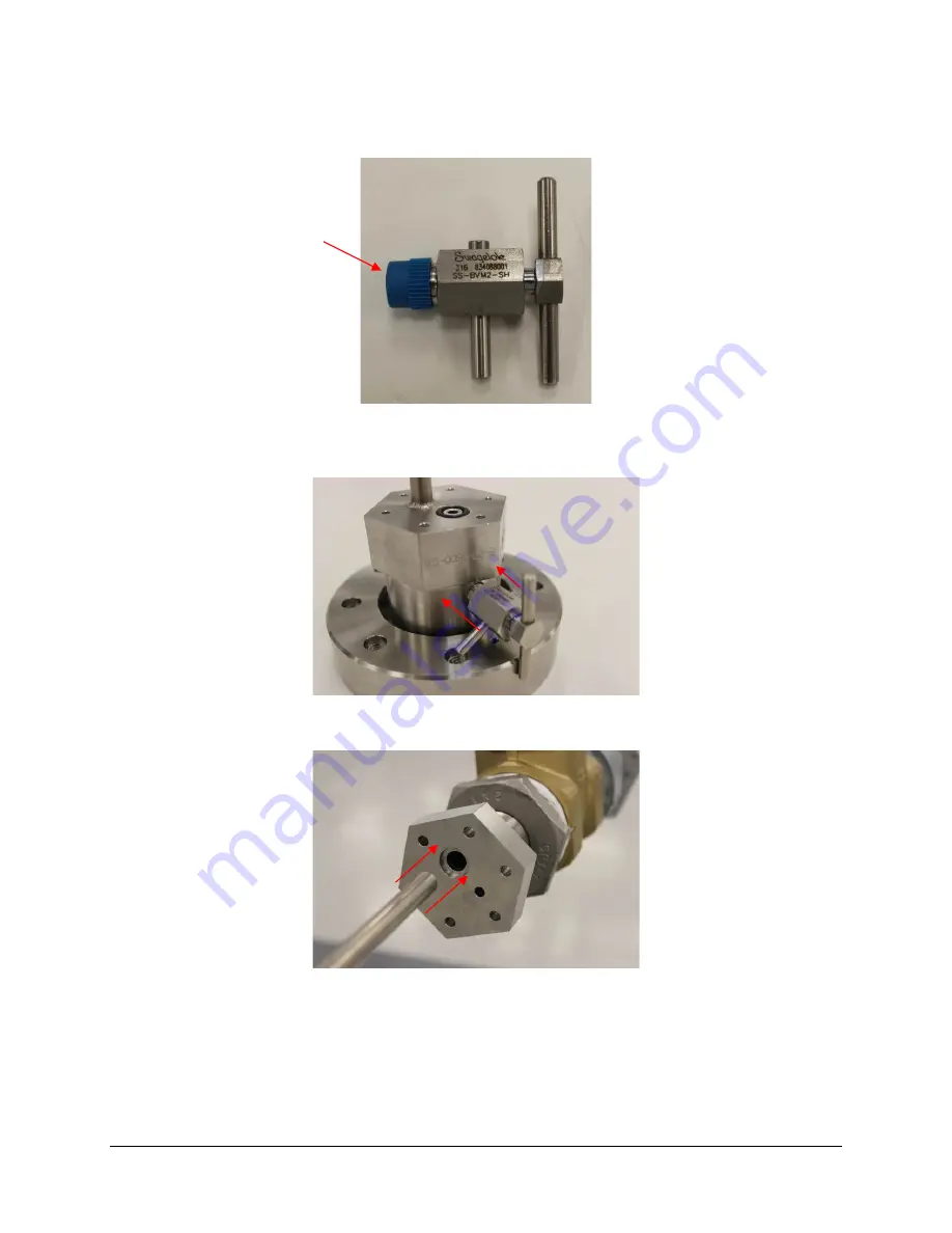
Locate the 1/8” Bleed Valve (PN 90-2395) and remove the protective cap and save it for
future use. Tape, grease, and tighten.
20.
Attach the 1/8” Bleed Valve to the port on the Instrument Side Adapter. Use an adjustable
wrench to fully tighten. Verify that the Bleed Valve is closed and pointing away from the
mounting ring
.
21.
Carefully insert the SSP pipe with attached Instrument Side Adapter into the open port on
the Drain Valve Side Adapter and gently slide it through until the SSP reaches the gate.
22.
Fully open the drain valve.
Remove
protective cap
Содержание SmartDGA
Страница 1: ...HARDWARE MANUAL SmartDGA...
Страница 99: ...SmartDGA Hardware Manual Diagrams Drawings 99 9 5 SmartDGA NEMA 4 Enclosure...
Страница 100: ...SmartDGA Hardware Manual Diagrams Drawings 100 9 6 Inline Mounting Plate...
Страница 102: ...SmartDGA Hardware Manual Diagrams Drawings 102 9 8 Assy Wall Mount SmartDGA EZHubTM...
Страница 103: ...SmartDGA Hardware Manual Diagrams Drawings 103...
Страница 104: ...SmartDGA Hardware Manual Diagrams Drawings 104 9 9 Assy Panel Mount SmartDGA EZHubTM...
Страница 105: ...SmartDGA Hardware Manual Diagrams Drawings 105...
Страница 106: ...SmartDGA Hardware Manual Diagrams Drawings 106 9 10 Assy Wall Mount LumaSMART iCoreTM...
Страница 107: ...SmartDGA Hardware Manual Diagrams Drawings 107...
Страница 108: ...SmartDGA Hardware Manual Diagrams Drawings 108 9 11 Assy Panel Mount LumaSMART iCoreTM...
Страница 109: ...SmartDGA Hardware Manual Diagrams Drawings 109...
Страница 110: ...SmartDGA Hardware Manual Diagrams Drawings 110 9 12 SmartDGA Instrument Sun Shade...
Страница 111: ...SmartDGA Hardware Manual Diagrams Drawings 111...


