SmartDGA Hardware Manual
SmartDGA System Installation
•
63
5.3.3
Connecting the
i
Core
The following are directions to electrically wire the LumaSMART
i
Core unit power, outputs, and
communication. The following sections outline the provided connections on the rear of the
LumaSMART
i
Core.
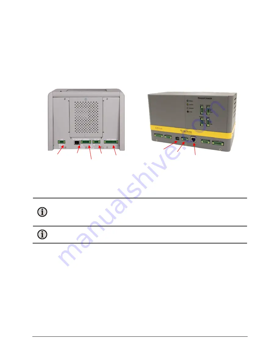
Communications Output
The SmartDGA system requires a communication connection from the EZHub to either an
i
Core or
PC. This can be done via Ethernet or RS485 connection.
Ethernet Connection
The Ethernet connector is the normal
RJ45
(CAT5) standard cable. A shielded
Ethernet cable must
be used. This cable is not provided as the required length will vary. The IP address for the Ethernet
connection can be supplied statically or by a DHCP server.
Note:
For an EZHub using a static IP, you could change the IP address using the
Commissioning Tool via RS485 or Ethernet. The new EZHub IP address will take affect
only after you power cycle the EZHub. It is recommended to power cycle the EZHub
immediately after you change the IP address.
Note:
The USB connection is only for uploading and downloading functions (such as
downloading data or uploading a new version of firmware).
When using Ethernet to communicate between the SCADA and the
i
Core, as well as between the
i
Core and EZHub(s), the use of an Ethernet switch (not provided) is required. An example of the
network topology in such a case is shown in the following figure:
Unused
Connection
Unused
Connection
AC In
Serial
(RS485)
Ethernet
RS485
Out
Ethernet
USB
Содержание SmartDGA
Страница 1: ...HARDWARE MANUAL SmartDGA...
Страница 99: ...SmartDGA Hardware Manual Diagrams Drawings 99 9 5 SmartDGA NEMA 4 Enclosure...
Страница 100: ...SmartDGA Hardware Manual Diagrams Drawings 100 9 6 Inline Mounting Plate...
Страница 102: ...SmartDGA Hardware Manual Diagrams Drawings 102 9 8 Assy Wall Mount SmartDGA EZHubTM...
Страница 103: ...SmartDGA Hardware Manual Diagrams Drawings 103...
Страница 104: ...SmartDGA Hardware Manual Diagrams Drawings 104 9 9 Assy Panel Mount SmartDGA EZHubTM...
Страница 105: ...SmartDGA Hardware Manual Diagrams Drawings 105...
Страница 106: ...SmartDGA Hardware Manual Diagrams Drawings 106 9 10 Assy Wall Mount LumaSMART iCoreTM...
Страница 107: ...SmartDGA Hardware Manual Diagrams Drawings 107...
Страница 108: ...SmartDGA Hardware Manual Diagrams Drawings 108 9 11 Assy Panel Mount LumaSMART iCoreTM...
Страница 109: ...SmartDGA Hardware Manual Diagrams Drawings 109...
Страница 110: ...SmartDGA Hardware Manual Diagrams Drawings 110 9 12 SmartDGA Instrument Sun Shade...
Страница 111: ...SmartDGA Hardware Manual Diagrams Drawings 111...


