background image

Chapter 7. Diagnosis Function 


7-6 


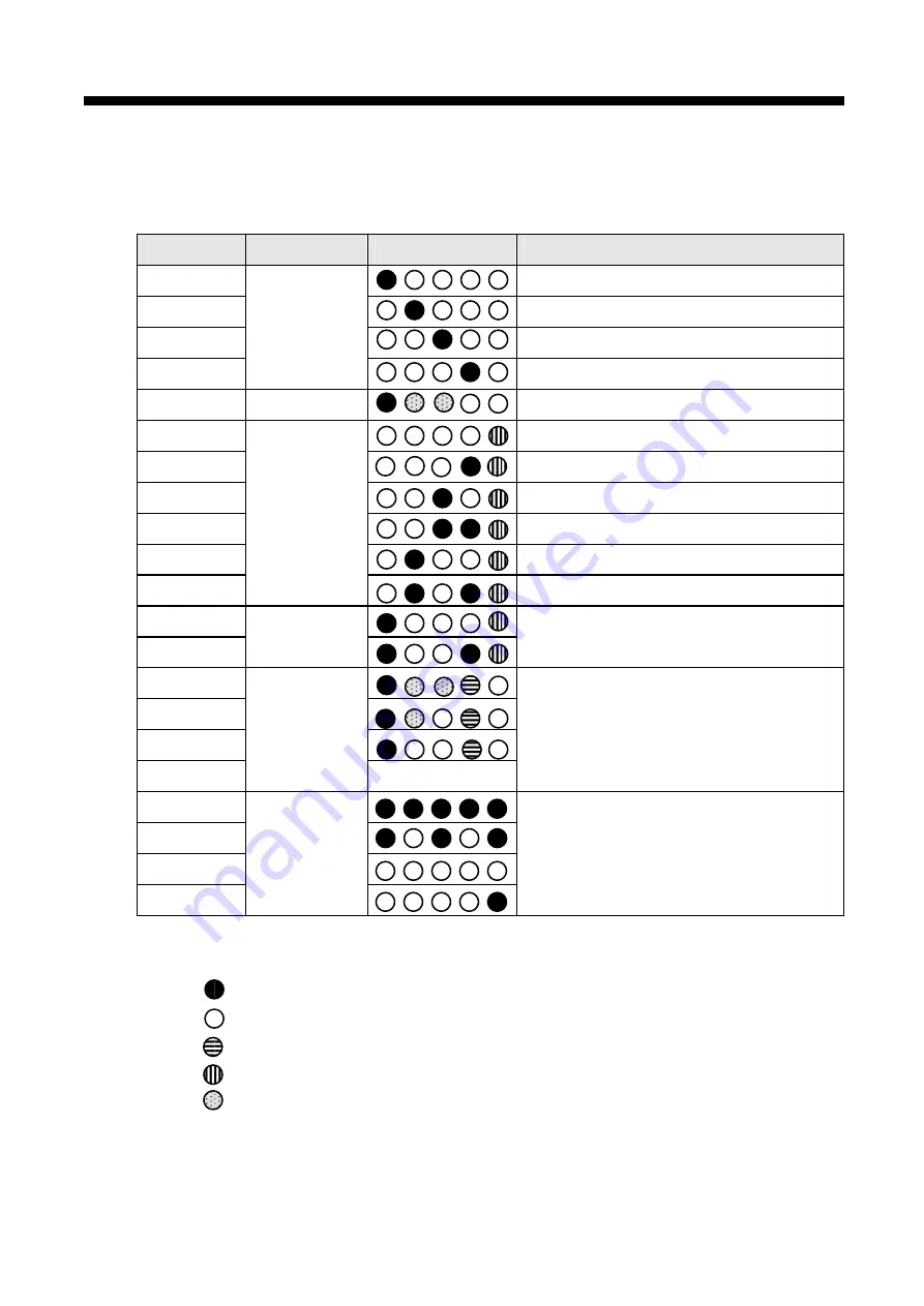
          [Table 7.1.3] LED indication specification of slave group 

Classification 

Error type 

LED status 

Error contents 

RSM_00 


Checking    inner memory 1 of module 

RSM_01 


Checking    inner memory 2 of module 

RSM_02  

Checking 

communication 

RSM_03 

Power on 


Checking special module common RAM 

RSM_04 

Normal 


Module communication is normal 

RSM_05 


Inner memory 1 error 

RSM_06 


Inner memory 2 error 

RSM_07  

Communication 

error 

RSM_08 


Write/Read special module error 

RSM_09 


Write/Read I/O module error 

RSM_10 

Hardware error 


Module equipment error, fuse error 

RSM_11  

RSM_12 

System 

operation error


System error during operation 

RSM_13  

RSM_14  

RSM_15  

RSM_16 

Abnormal 


 Cable shout/open 

Not suitable for cable length 

Hardware error 

Network configuration status error 

RSM_17  

RSM_18  

RSM_19  

RSM_20 

Error that 

can

t be 

recovered 


Hardware error of communication module 


 LED location is RUN, TOKEN, TX/RX, FAULT, SYS FAULT from left. 

                                        On 

                                        Off 

                    Flicker with 1 second period 

                                        Non-periodical flicker or off 

                                        Non-periodical flicker 


Содержание G0L-GWRA

Страница 1: ...llybeforeinstalling wiring operating servicingorinspectingthisequipment y Keep this manual within easy reach for quick reference Rnet I F Programmable Logic Controllers G3L RU R EA G4L RU R EA G6L RU R EA G7L RUEA G0L GWRA ...

Страница 2: ...in the user s manual have the following meanings indicates handling and directions probably causing a danger If you find this mark you should read it carefully and follow the directions to avoid danger indicates the possibility of electric shock under a certain condition The user s manual even after read should be kept available and accessible to any user of the product Caution This symbol indicat...

Страница 3: ...orrectly installed it may cause incorrect operation trouble or fall Analog I O signal or pulse I O cable should be installed at least 100mm away from high voltage power cable so that such cables may not be affected by noise or magnetic field change It may cause incorrect operation due to noise If huge vibration exists in the installation place it is necessary to take a measure PLC may not be direc...

Страница 4: ...oltage not rated voltage or wiring incorrectly may cause a fire or trouble Firmly tighten the screws for wiring with a specified torque Loosely tightened screw may cause short circuit or incorrect operation Make sure to use the exclusive PLC type 3 grounding for FG terminal grounding Without grounding it may cause incorrect operation A special caution should be paid so that no wiring impurities ar...

Страница 5: ...t may cause an electric shock incorrect operation Do not detach PCB from the case nor alter it It may cause a trouble incorrect operation damages on product or a fire Installing or detaching the module should be executed with every external power off It may cause an electric power or incorrect operation When using a cellular phone or radio set stay at least 30cm from PLC It may cause an incorrect ...

Страница 6: ...Date Description Modified Page V 1 0 April 04 First edition published V 1 1 July 05 CI mark is changed The No of user s manual is indicated on the right side of back cover ⓒ LS Industrial Systems Co Ltd 2004 All Rights Reserved ...

Страница 7: ...et LED signal name and indication content 3 9 3 2 5 Rnet station no setting 3 9 3 2 6 Rnet mode setting 3 10 Chapter 4 Transmission specifications 4 1 Transmission Specifications 4 1 4 1 1 Transmission specifications of Master module 4 1 4 1 2 Transmission specifications of Slave module 4 2 4 2 Cable specifications 4 3 4 2 1 Twisted pair cable 4 3 4 3 How to connect communication cable 4 4 4 3 1 E...

Страница 8: ...2 5 System flag for remote module 6 29 6 3 Slave Dedicated Function Block Service 6 30 6 3 1 Slave special module function block 6 30 6 3 2 How to use special module function block 6 33 6 4 Communication module flag application 6 37 6 4 1 Flag type 6 37 6 4 2 Imprtant flag used in the Rnet 6 37 6 4 3 How to use the flag in the GMWIN 6 38 6 4 4 Special module access by using _NETx_LIV n _NETx_RST n...

Страница 9: ...E02 02 Slave mounting and writing interface error during operation 9 8 9 2 7 Error code E03 01 High speed link parameter error 9 9 9 2 8 Error code E03 02 High speed link not run 9 10 9 2 9 Error code E03 03 RUN link contact of high speed link not ON 9 11 9 2 10 Error code E03 04 Trouble contact of high speed link ON 9 12 9 2 11 Error code E04 01 Execution error of Rnet communication command 9 13 ...

Страница 10: ...nance easiness of change of system This network supports the electric network Twisted pair cable that is cheap and easy to install for diversity of network configuration And we are supporting the repeater option module for special purpose The Rnet module can be used in both GLOFA and MASTER K PLC and applied diversely according to system 1 GMWIN V3 0 and KEL WIN V2 0 are used for this manual 2 To ...

Страница 11: ...nication module name Base G3L RUEA GM2 CPUB GM3 K1000S G4L RUEA GM4 K300S G6L RUEA GM6 K200S Master module RMM Twisted pair Electric Interface G7L RUEA GM7 K80S G3L RREA GM3 K1000S G4L RREA GM4 K300S G6L RREA GM6 K200S GRL D22A Smart I O GRL D24A Smart I O GRL TR2A Smart I O GRL TR4A Smart I O GRL DT4A Smart I O Rnet Slave module RSM Twisted pair Electric Remote I O GRL RY2A Smart I O 1 2 Type of ...

Страница 12: ...ad of CPU of PLC refreshes I O module mounted on remote station by receiving I O data from master station Rnet Fieldbus is the lowest network connecting the control device and electric device and adopts the 3 layers among OSI 7 layer 3 layers consists of physical layer which consists of H2 1 Mbps electric H1 31 23 Kbbs electric optical and wireless etc the data link layer which adopts scheduled an...

Страница 13: ...net is 110Ω 1 2W High speed link HS Link This is used among GLOFA PLC communication modules only and used to transmit and receive data at high speed and executes communication by setting high speed link parameter of GMWIN KGLWIN GMWIN GLOFA PLC Programming and Debugging Tool This software enables user to program in order to fit to the system and to download run stop and debug in GLOFA PLC CPU modu...

Страница 14: ...ms Static electric discharging Voltage 4kV Contact discharging IEC 61131 2 IEC 61000 4 2 Radiation electric field noise 27 500 MHz 10V m IEC 61131 2 IEC 61000 4 3 Segment Power module Digital input output 24V or more Digital input output less than 24V Analog input output communication interface 7 Noise Fast transient burst noise Voltage 2kV 1kV 0 25kV IEC 61131 2 IEC 61000 4 4 8 Ambient conditions...

Страница 15: ...indicating section RUN Indicates the status of CPU module and interface LAS Indicates that communication module is performing LAS function TOKEN Indicates whether communication module has a token or not TX RX Indicates whether communication module is transmitting receiving or not FAULT Flickers when the error that normal operation is not possible occurred in i i d l Mode setting switch Sets operat...

Страница 16: ...orming LAS function TOKEN Indicates whether communication module has a token or not TX RX Indicates whether communication module is transmitting receiving or not FAULT Flickers when the error that normal operation is not possible occurred in communication module Type name indicating section Indicates type name of communication module Mode setting switch Sets operation mode of communication module ...

Страница 17: ...AS performing LAS function Master module LINK I F whether there is Tx Rx data Station no inner part Station no 0 63 decimal indication X10 indicates 10 digit of station no 0 6 X1 indicates 1 digit of station no 0 9 Connector CON1 2 fieldbus cable connector 9 pin plug type G7L RUEA PROGRAMMABLE LOGIC CONTROLLER x10 x1 ADDRESS ERR LAS TOKEN LINK I F CON2 CON1 ...

Страница 18: ...s of communication module TOKEN Indicates whether communication module has a token or not TX RX Indicates whether communication module is transmitting receiving or not FAULT Flickers when serious error of system itself or I O module error occurred Mode setting switch Sets operation mode of communication module Communication connector Connector for electric cable connection to connect communication...

Страница 19: ...Station number setting switch Sets master station number of remote communication module Set in the range of 0 63 station using decimal Output of emergency data Specifies output data type when communication failure by cable cut off See 3 2 6 Fnet mode setting X10 X1 ...

Страница 20: ...of CPU module and interface TOKEN Indicates whether communication module has a token or not TX RX Indicates whether there is TX RX data or not FAULT Flicker when it can t start normally because of error ERROR Flicker when system error or I O error occur Type name indicating section Indicates type name of communication module Mode setting switch Sets the operating mode of communication module Commu...

Страница 21: ...es GMWIN KGLWIN connection normal flicker ERR indicates error normal off Communication connector 5Pin fieldbus cable connector 9Pin connector GMWIN KGLWIN connection cable inner cover Power DC 24V power and FG terminal unit inner cover Rnet G0L GWRA PWR TRX ERR 1 G0L GWRA s station no is set as 63 automatically when configuring Rnet system Note ...

Страница 22: ...mmunication module Normal Abnormal TOKEN Indicates whether communication module has token or not Has Does not have TX RX Indicates whether communication module is transmitting receiving or not In proceeding Flicker FAULT Indicates whether communication error exists or not Abnormal Normal G3L RREA G4L RREA G6L RREA SYS FAULT Indicates whether system error or I O module error occurred or not Abnorma...

Страница 23: ...Description G3L RREA G4L RREA G6L RREA 0 5 2 7 10 0 5 2 7 1 1 Station number can be set from 0 to 63 Decimal 2 Station number setting Factory default is 0 Switch Setting X 10 Sets ten s figure of station number X 1 Sets one s figure of station number 3 2 6 Rnet mode setting 1 Mode of master module Applied device type Detailed drawing of mode switch Description G3L RUEA 0 5 2 7 0 ON LINE MODE G4L R...

Страница 24: ...e Check it 3 Emergency data output setting except GM6 Rnet slave module doesn t support the emergency data output Applied device type Emergency data switch Contents G3L RREA 1 2 3 ON 4 This switch is not used G4L RREA 1 2 ON This switch is not used Mode function 0 GLOFA mode default mode 1 MASTER K mode z Because GLOFA MASTER K use the different I O address mode is divided Check the mode before us...

Страница 25: ...0 GM MODE This switch is not used MODE 1 MK MODE This switch is not used MODE 2 GM E MODE This switch is not used G6L RREA MODE 3 MK E MODE This switch is not used Note 1 User can input user defined data for communication error in GMWIN function block program of GLOFA and in KGL WIN or KDL 150S of MASTER K 1 2 ON 1 2 ON 1 2 ON 1 2 ON ...

Страница 26: ...Common in Rnet Encoding type Manchester Biphase L Transmission distance per segment Max 750m Transmission distance during using repeater Max 750m 6 repeater 1 5 25 km Electric Transmission line Twisted pair shielded cable Max number of station connection Master slave 64 station At least one master should be connected Max size of protocol 256 byte Access type of communication right Circulated Token...

Страница 27: ...ps Encoding type Manchester Biphase L Transmission distance per segment Max 750m Transmission distance during using repeater Max 750m 6 repeater 1 5 25km Electric Transmission line Twisted pair shielded cable Max number of stations connected Link Master Class Remote Slave Class 64 Max size of protocol 256 byte Access type of communication right Circulated Token Passing Communication type Connectio...

Страница 28: ...ics Item Unit Characteristic Test Condition Conductor resistance Ω km 21 8 or less Normal Temp Withstanding voltage DC V min Withstands at 500V for 1 minute In air Insulation resistance MEGA Ω km 1 000 or more Normal Temp Static electricity capacity pF m 45 or less 1 kHz Characteristic impedance Ω 120 12 10 MHz Characteristics in appearance Number of core CORE 2 Specification AWG 18 Configuration ...

Страница 29: ... and high current should not be allowed 6 7 6 7 S h ie ld w ire A c o m m u n ic a tio n m o d u le B c o m m u n ic a tio n m o d u le 5 P in m o d u le 6 1 4 2 5 7 S h ie ld w ire 1 5 9 P in m o d u le Verify pin No marked in connector to connect Figure 4 3 1 Rnet Electric Cable connection method 4 3 2 Electric twisted pair cable connector connection Connector is accessory parts which connects e...

Страница 30: ...0Ω 1 2W of accessory parts electric module only should be attached at the start and end of network Terminal resistance is attached inside of electric optical converter G0L FOEA and repeater G0L FREA which are installed at terminal of electric network Therefore do not connect terminal resistance separately from external Connector case should not be connected with terminal resistance In case that ca...

Страница 31: ...nager Ethernet 10 100Mbps Rnet 1Mbps 64 station 750m twisted pair cable GM2 GM3 GMWIN RS 232C GM3 remote I O GM4 remote I O GM6 remote I O SmartI O Rnet GRL D22A GRL TR2A GM4 SmartI O Rnet GRL D24A GRL TR4A GRL DT4A GRL RY2A SmartI O Rnet G0L GWRA Chapter 5 system configuration 5 1 Chapter 5 system configuration 5 1 GLOFA MASTER K PLC network system ...

Страница 32: ...art I O GRL RY2A GRL D24A GRL DT4A GRL TR4A Smart I O GRL D22A GRL TR2A G0L GWRA Smart I O GRL RY2A GRL D24A GRL DT4A GRL TR4A Smart I O GRL D22A GRL TR2A G0L GWRA Smart I O GRL RY2A GRL D24A GRL DT4A GRL TR4A Smart I O GRL D22A GRL TR2A G0L GWRA GLOFA GM3 G3L RREA GLOFA GM3 G3L RREA GLOFA GM3 G3L RREA GLOFA GM4 G4L RREA GLOFA GM4 G4L RREA GLOFA GM4 G4L RREA GLOFA GM3 G3L RREA GLOFA GM4 G4L RREA G...

Страница 33: ... K series setting 1 Setting range of Rnet I F module Maximum High Speed Link Contact No Rnet Master Type Max communication contact no Max sending contact no Max block no Max contact no per block G3L RUEA 3 840 word 1 920 word 2 0 1 60 word G4L RUEA 3 840 word 1 920 word 2 0 1 60 word G6L RUEA 3 840 word 1 920 word 2 0 1 60 word Rnet I Fmodule G7L RUEA 3 840 word 1 920 word 2 0 1 60 word Communicat...

Страница 34: ...ormation Individual information Key word name HS Link no 1 2 3 4 _HS RLINK _HS LTRBL _HS TRX n n individual parameter no 0 63 _HS MOD n n individual parameter no 0 63 _HS ERR n n individual parameter no 0 63 _HS STATE n n individual parameter no 0 63 Data type BIT BIT BIT ARRAY BIT ARRAY BIT ARRAY BIT ARRAY Monitoring available available available available available available Used for programming...

Страница 35: ...n module to equip according to PLC CPU GLOFA GM2 CPUB GM4 CPUC can equip max 8 GM4 CPUB can equip max 4 and GLOFA GM4 CPUA GM6 can equip max 2 GM7 can equip max 1 communication module Module equipment relationship according to CPU type Classification installable communication module Max no GLOFA GM2 CPUB G3L RUEA 8 GLOFA GM3 G3L RUEA 4 GLOFA GM4 CPUA G4L RUEA 2 GLOFA GM4 CPUB G4L RUEA 4 GLOFA GM4 ...

Страница 36: ...d the High Speed Link parameter setting basic window like the following figure opens and it has the following initial value Parameter setting initial screen The High Speed Link initial screen consists of two items Link set and Entry list The setting method and function for each item is as follows ...

Страница 37: ... Rnet Slot No Set one of 0 7 for slot number that communication module to mounted right side of CPU module is 0 slot Self station No Input the self station no set in the station no switch in front of communication module The self station no of Rnet always should be 0 2 G7L RUEA link set Network type select the GLOFA Rnet Slot No This is not activated Self station No The self station no always shou...

Страница 38: ... Speed Link operation If the setting of the High Speed Link parameter is finished write the parameter to PLC CPU after compiling it and enable the High Speed Link If the above process is done High Speed Link service starts High Speed Link starting sequence is as follows 1 Write parameter Parameter download screen Save the High Speed Link parameter written by the user in the project file of the GMW...

Страница 39: ...nk starting After Link Enable Setting the High Speed Link is executed The Link Enable Setting should be done on the Stop mode Once High Speed Link is executed it operated regardless of PLC mode The parameter and information of the Link Enable Setting is saved in the CPU via the battery though the power is cut ...

Страница 40: ... function of GMWIN The sequence is as follows Select Variable monitor on the view menu Select Flag on the variable monitor screen like the follo wing figure Select the flag on the flag list and register the flag that the user wants to monitor Since _HSxSTATE n _HSxERR n _HSxMOD n _HSxTRX n is ARRAY flag input the registration no of parameter the user wants to monitor Note 1 x means the high speed ...

Страница 41: ... screen To change the High Speed Link no to monitor click the right button on the Link Parameters menu and click Select link parameter Total information about run link link trouble is displayed on the upper screen Mode operation mode communication TRX status each information about error are displayed per parameter item Link trouble information Link individual information TRX status information Run...

Страница 42: ...ameter can be set by selecting the link parameter on the project screen of KGLWIN The setting sequence and function per each item is as follows 1 Setting the project of KGLWIN The following figure is parameter basic screen invoked when selecting the parameter window KGLWIN parameter basic screen in case of K200S 2 Link parameter basic setting If you select Link1 on the KGLWIN parameter basic scree...

Страница 43: ...pter 6 Communication Function 6 11 Link parameter basic screen 3 Basic setting of K80S project and link parameter The following is parameter basic screen invoked when selecting the K80S s parameter window ...

Страница 44: ... in case of K80S On the parameter basic screen of the above figure if you select Comm communication parameter setting window shows If you select FIELDBUS menu as Master and select List high speed link parameter basic screen shows Communication parameter setting screen ...

Страница 45: ...CPU Module equipment relation per CPU type Classification Comm Module Max equipment no Reference K1000S G3L RUEA 4 K300S less than v2 2 G4L RUEA 2 K300S more than v2 2 G4L RUEA 4 K200S G6L RUEA 2 K80S G7L RUEA 1 Available to mix each communication module Link whether executing the communication module link Self station no self station no should be 0 Slot slot no where communication module is equip...

Страница 46: ... following table indicates how to set the station no How to set the station no Communication type Station no Station no range Remote In Remote Out Remote station no 1 63 Block No this parameter classifies the data of diversity block to send receive diversity data at the one station It is available to set the one TRX block per one station Module Type Remote In and Remote Out are available Remote Ou...

Страница 47: ...d unit is word 16 point It is available to set up to 60 word but Rnet supports 2 word Because current Smart I O supports max 2 word Period High speed link executes the communication at the end of PLC program according to parameter set by the user So if scan time of PLC program is short less than ms communication module executes the communication according to program scan Because of this communicat...

Страница 48: ...n Monitor Flag Another is monitoring the entire information by selecting the high speed link parameter on the Read Information menu Flag monitor It is available to use the flag monitor function by selecting Flag on the Project Monitor If you click the flag button and button the following screen shows Register the flag you want to monitor If monitor function doesn t work check whether this mode is ...

Страница 49: ...ormation about high speed link parameter as follows High speed link parameter monitor R02 R03 means the remote Smart I O 2 station and 3 station and S00 S01 means the block no No 0 parameter means that it sends the data M000 of self station to remote Smart I O 2 station P000 through no 0 block No 2 parameter means that it sends the data M000 of self station to remote Smart I O 3 station P000 ...

Страница 50: ...f you select Online Read Information Link Information you can monitor the link status of communication module according to slot If you select module you want to monitor and click Network Information button you can see the connection status of all Rnet network connected with relevant module Except K80S ...

Страница 51: ...on 1 All station set in the parameter are RUN mode there is no error 2 All data block set in the parameter is normal 3 The parameter set in the each station set in the parameter is normal Once RUN_LINK is turned on it keeps its value as long as it stops by Link Disable _HSmLTRBL Bit Dx600 1 HS link s abnormal information LINK_TROUBLE This flag is turned on when _HSmRLINK is on and communication st...

Страница 52: ...f parameter is normal or not _HSmERR k k 0 63 Bit Array Dx613 0 Dx616 15 Status information of station set in the k data block at the HS link parameter normal 1 abnormal 0 Indicates whether there is error or not at the station set in the k data block of parameter HS link detail flag when m 1 3 HS link type D area address reference High Speed Link2 m 1 Dx620 Dx633 High Speed Link3 m 2 Dx640 Dx653 H...

Страница 53: ...odule and PLC A is master PLC C is using the Rnet remote I F module They are connected each other To access PLC A choose communication module station number of PLC A other station number to connect and slot number of G3L RREA slot number that RREA module is currently mounted at Remote 1 connection of program tool Then remote connection can be established by RS 232C and Rnet This state is identical...

Страница 54: ...n menu from upper menu of program and choose Remote 1 in connection level then following screen will be displayed Network type setting Choose type according to network that remote 1 connection is made choose GLOFA Fnet Rnet because remote 1 connection is connected with Rnet Station no setting Specify station number of communication module mounted in PLC which makes remote 1 connection Station numb...

Страница 55: ...on is failed following message is displayed Communication line error internal protocol error When setting value of remote connection is not proper If PLC that remote 1 connection is made is different from CPU type of project currently opened following message is displayed and only restricted On line menu can be selected ...

Страница 56: ... station G0L GWRA to GM1 GM7 s PLC is possible GM4 GM6 don t have above function and G0L GWRA s station no is always 63 When using the G0L GWRA be careful that station no 63 is not repeated in the Rnet network Caution when remote 1 connection in GMWIN 1 If currently opened project in GMWIN is different from CPU type connected with remote 1 following items are not supported 1 Writing of program and...

Страница 57: ...t relation to program Time chart monitor of monitor Link parameter of monitor High speed link monitor Forced I O information Link enable setting Flash memory Link information Mode conversion 4 Flash memory 5 Link enable setting 6 I O skip 4 Rnet remote connection is supported up to remote 1 Remote connection of more than 1 is impossible 5 Remote 1 connection from master to slave is possible and ca...

Страница 58: ... 1 connection KGL WIN should be in off line state In this state select Connection option at the Project Option menu Method of Connection select RS 232C and communication port of PC Depth of Connection select Remote 1 and Fnet Rnet type Slot no setting input slot number of communication module mounted in PLC of self station which makes remote 1 connection Station no setting input station number of ...

Страница 59: ...e Change the PLC type of the project Remote 1 connection state is same with connection the RS 232C cable is moved All menus in Online are available K1000S remote module G0L GWRA module have RS 232C cable So K1000S remote module can make the remote 1 connection to K1000S K200S PLC K300S K200S don t have a remote connection connector Caution when KGL WIN remote 1 connection 1 Currently opened projec...

Страница 60: ... connection I O information monitor on the Online menu Checking the I O information of remote PLC is available 1 I O monitor I O monitor function provides the information of Rnet remote I F module The following screen is displayed if you select Read Information I O Information When monitoring the information of special module select the special module you want to monitor and press the module infor...

Страница 61: ...tion to program Time chart monitor of monitor Link parameter of monitor High speed link monitor Forced I O information Link enable setting Flash memory Link information Mode conversion 4 Link enable setting 5 Rnet parameter Rnet information 6 2 5 System flag for remote module Information saved in the inner memory of remote module can be monitored by RSM s flag monitor and HS link and communication...

Страница 62: ...e function block Slave can equip the following special module D A conversion module A D conversion module RTD module High speed counter module and equip able module type is 8 For more detail refer to the Chapter 8 table 8 1 2 Slave special module function block controls the special module equipped at the slave NET_NO ST_NO is added at the previous function block input and ERR NDR is added at the p...

Страница 63: ...ication module among modules equipped at the self PLC that communicate with the slave Namely it means the slave s master communication module 0 7 ST_NO Input Indicates the station no of slave that equips the special module 0 63 NDR Output Indicates the result of function block operation It is turned on when normal operation and keeps its value until next scan execution On Off ERR Output Indicates ...

Страница 64: ...x_RD x 0 1 HSCR1RD O O X X 2 channels HSCR0SET X X 0 X 1 channels HSCRx_SET x 0 1 HSCR1SET O O X X 2 channels HSCR0WR X X 0 X 1 channels HSCRx_WR x 0 1 HSCR1WR O O X X 2 channels RTDR2INI X X 0 X 4 channels RTDxINI x 2 3 RTDR3INI O O X X 8 channels RTDR2RD X X 0 X 4 channels RTDxRD x 2 3 RTDR3RD O O X X 8 channels TCR2INI X X 0 X 4 channels TCRxINI x 2 4 TCR4INI O O X X 16 channels TCR2RD X X 0 X ...

Страница 65: ... station like the follow table in case other station except mother station accesses the slave special module it may cause error Special module should be accessed by mother station Table 6 3 2 Slave operation according the mother PLC mode CPU MODE Slave HS link note Slave special module access Slave I O refresh RUN STOP X PAUSE DEBUG 2 Program Special module control through slave uses communication...

Страница 66: ...s the special module of slave in the system like above figure first set the mother station no setting switch in the slave module as 1 After mother station setting write the slave special module function block service program through the GMWIN program Figure 6 3 2 A and Figure 6 3 2 B are example of program Master RUEA 1 station Slot no Executes every 200ms until execution of FB Base no where A D m...

Страница 67: ...scan due to delay of slave power supply or problem about communication line Therefore program should be written to execute the next step after checking the result of FB by using NDR output point like example This is applied for other special module access program Slot no of master stion 1 Slave station no Base no where D A module is equipped Slot no where D A module is equipped ...

Страница 68: ...ram The FB is also executed every 200ms 3 STATUS information The result of FB execution can be known through NDR ERR output contact point In case of normal operation NDR is on and ERR is off In case of abnormal NDR is off and ERR is on Error code is shown at the STAT For detail of slave special module access error refer to the appendix A1 ...

Страница 69: ... on and data TRX is normal through the communication cable 2 _NETx_RST n It indicates information about power recovery It will be on if power is recoved from power cut or cable cut 6 4 2 Imprtant flag used in the Rnet Type Data type Access allowance Reference _NETx_LIV n range n 0 63 USINT Read only _NETx_RST n range n 0 63 USINT Read write FSM FMM Common flag x used in the flag indicates the slot...

Страница 70: ... by communication initialization may not be done because of communication error it is necessary to execute the initializataion continuously until completion of initialization 2 In case of power recovery from power cut initialization is needed again So program that monitors the power is necessary against this 3 FB that reads writes the data from to special module is executed at the rising edge of R...

Страница 71: ...should be completed in order to execute the READ WRITE command For that NDR output B contact point is used as Request input and initialization is repeated every 200ms until completion of initialization Initial F B is executed until completion of initialization Flag that checks the remote station s operation Program that initializes the TC module When completion of initialization NDR is on Program ...

Страница 72: ...e used with program of Figure 6 4 1 A Figure 6 4 1 B Restart program when power recovers from power cut _NET0_RST 2 and _NET0_LIV 2 is used to monitor when other station recovers from power cut and at this time each NDR output of F B is reset and initialization program is executed again in Figure 6 4 1 B Since _NET_RST 2 flag keeps its value until ther user s reset command _NET_RST 2 flag should b...

Страница 73: ...4L RUEA G6L RUEA RUN LAS TOKEN TX RX FAULT G7L RUEA ERR TOKEN LAS LINK I F 2 LED indication description 1 RUN indicate that communication with PLC CPU is normal On interface with PLC is normal Off interface error or interface stop Since flicker period changes according to PLC scan when PLC scan is long more than 200ms or PLC has more than two communication module and exchange a lot of data LED is ...

Страница 74: ...the error of communication module It is off during normal operation It flickers every 1 second when communication can t start because of error and 5 LEDs LES 0 RUN LED4 FAULT indicates the type of error 6 LINK I F as an interface LED it flickers when Rnet module communicates with PLC CPU When HS link is RUN and it is normal operation it looks like always on When HS link is disabled it flickers eve...

Страница 75: ...or RMM_11 Interface error 1 RMM_12 Interface error 2 RMM_13 Hardware error Interface error 3 RMM_14 RMM_15 System operation error System error during operation RMM_16 Network configuration status error RMM_17 Duplicated station no terminal resistance RMM_18 Cable open short RMM_19 RMM_20 Cable length error or hardware error RMM_21 Abnormal communication Network configuration status error RMM_22 In...

Страница 76: ...le hardware error LED location is ERR TOKEN LAS LINK I F from left 7 1 3 Rnet I F slave module LED indication 1 Relevant model G3L RREA G4L RREA G6L RREA RUN TOKEN TX RX FAULT SYS FAULT 2 LED indication description 1 RUN indicates that I O check I O refresh is executed normally In case of power error I O refresh error special module access error it is off On salve is normal Off slave is abnormal O...

Страница 77: ...r in the link module Off normal operation If it flickers intermittently it has the problem Check the communication module communication cable terminal resistance connection status duplicated station no Is terminal resistance connected normally Is cable connected firmly Is shield wire is connected properly Is cable and terminal resistance specification proper Is total length of cable less than 750m...

Страница 78: ...or RSM_07 Communication error RSM_08 Write Read special module error RSM_09 Write Read I O module error RSM_10 Hardware error Module equipment error fuse error RSM_11 RSM_12 System operation error System error during operation RSM_13 RSM_14 RSM_15 RSM_16 Abnormal Cable shout open Not suitable for cable length Hardware error Network configuration status error RSM_17 RSM_18 RSM_19 RSM_20 Error that ...

Страница 79: ...on of basic base Remote I O G6L RUEA 2 I O GM6 K200S G6L RREA 1 CPU location of basic base Remote I O GM7 G7L RUEA 1 Basic base I O 8 1 1 Install Rnet I F master module 1 In the types of master module there are electric communication modules of G3L RUEA G4L RUEA G6L RUEA and G7L RUEA Communication module can be mounted up to 4 in GM1 GM2 and GM3 PLC and these can be mounted only in main base When ...

Страница 80: ... 1 2 module model name for slave configuration Available module name Unavailable module name Itme Itme Type name Cordinate module GM1 CORA All I O module Interface module ALL A D D A conversion module Interupt module G F INTA TC RTD module Fnet Enet Dnet Pnet module G L FUEA FUOA G L EUEA DUEA PID control module G F PIDA Analog timer G F AT A Cnet module G L CUEA High speed counter module When usi...

Страница 81: ...d install terminal resistance at CON1 or CON2 if this module is terminal 110Ω 9 Electric module cable should be connected tightly using screw of cable connector If mounted station is not terminal both side of cable can be connected any of CON1 and CON2 10 Turn the power on after connecting communication cable check whether this module operates normally through LED operation status If it is normal ...

Страница 82: ...rough communication cable should not be a closed circuit 9 When connecting the communication cable with long distance keep the distance from power line or inductive noise 10 Shield wire should be connected with body of 9 pin connector Refer to the 4 4 1 11 If LED operation is abnormal see chap 9 Troubleshooting of this manual to check the cause of the error If the error occurs continuously after m...

Страница 83: ...ry of CPU module connected Is mounting of all base modules perfect Ö See product manual according to each PLC type Connection status of Communication cable Is connection status of communication cable perfect Is connection type of each cable open loop Module mounting Is mounting status of communication module which is mounted in basic base perfect Switch checking Is the status of mode switch On lin...

Страница 84: ...Check whether LED status of communication module is normal or not Ö If abnormal see Chap 9 Troubleshooting of this manual Programming Programming is prepared in GMWIN KGLWIN and it is written into CPU module Properly use flags that are related to emergency action for communication cut off during communication with other station and monitoring of other station Sequence check Checks operation of com...

Страница 85: ...rdware error of module See Appendix LED indicati on FAULT LED Light off check Regular flash means system error and intermittence flash means communication error See Appendix 2 Rnet I F slave module Table 8 4 1 B Items of daily check Items to be checked Contents Criteria of decision Action to take Cable connection status Release of cable Shall not be any release Tighten the cable Release of screw S...

Страница 86: ...l specification If it is used in a class environment of class is used as standard Release shaking Shake communication module Shall not be any release or shaking Tighten the screw Module status Attachment of dust and foreign matter Visual inspection Shall not be any attachment Remove Release of terminal screw Tighten using driver Shall not be any release Tighten Gap between compression terminals Vi...

Страница 87: ...ndication of each module E00 02 RMM_11 RMM_13 MCM_11 Interface diagnosis error with PLC among LED indication of each module E00 03 FOU_41 FOU_42 FOU_43 FOU_44 FOU_51 FOU_52 FOU_61 FOU_62 Power and hardware error of FOU group occurred E00 04 RSM_08 RSM_10 Initialization of I O and special module in slave group Table 9 1 B Abnormal communication status of communication module Error code Error indica...

Страница 88: ...to On during high speed link After setting link enable and _HSxRLNK of high speed link is set to On when HSxLTRBL is set to On by the problem of PLC and communication in normal status Table 9 1 E Abnormal operation of communication command service function Error code Error indication Error contents E04 01 When service is performed by Rnet ERR contact of communication command is set to On and the v...

Страница 89: ...er normal Does installation environment fit to specification Restart the power Does the same error occur It is a hardware error of this module Contact Service station Does it perform normal operation Perform troubleshooting for appropriate error Hardware error of self diagnosis Check power voltage Complement installation environment Yes Yes Yes No No No Yes No End ...

Страница 90: ... normal Is communication module exactly mounted in main base Yes Yes No No Does installation environment fit to specification Check power voltage Yes Exactly mount communication module into main base Change the condition of ambient environment so as to be in the range of general specification Has the connector pin of communication module any error Yes No Correct connector pin No End ...

Страница 91: ...I O module Contact Service station Check power voltage Exactly mount communication module and I O module into base Change the condition of ambient environment so as to be in the range of general specification Has the connector pin of communication module error Remove the module that can t be mounted in remote I O station Correct connector pin No Is base connection cable connected well Securely con...

Страница 92: ...ombined No Are Tx Rx connectors connected to right position Is using method of EOC repeater and active coupler correct Connect terminal resistance at both terminal of network Reduce the cable length within specified range Use repeater if cable length is longer than specified range Change the station number so as not to be duplicated Use single type of specified cable Is the entire network a closed...

Страница 93: ...o Is installation environment out of the specification of this product Securely mount communication module Check power voltage Is communication module securely mounted in base No Is authorized power normal Securely mount error module Perform troubleshooting for CPU This is the hardware error of communication module or CPU Contact A S center Change the conditions of ambient environment so as to be ...

Страница 94: ...o be complied with general specification range Exactly mount communication module and I O module into base Does installation environment fit to specification Are communication module and I O module exactly mounted in base Correct connector pin This is the hardware error of communication module or I O module Contact A S center Securely connect the cable No End Yes Yes Yes Check power voltage Has th...

Страница 95: ...ing method of station number for each registration item correct Correct the link setting according to network type station number and slot number of appropriate slot Download parameter again Reduce transmission items by referring to the description of high speed link function No End Yes Yes Yes Repair the battery and download program and parameter No Are there duplicated blocks numbers among regis...

Страница 96: ...No Is setting method of station number for each registration item correct Correct the link setting according to network type station number and slot number of appropriate slot Download parameter again Check and correct it according to the flow of error code E01 01 Yes End Yes Yes Set appropriate link enable to On No Is TR area relevant among registration items Adjust the range of Tx Rx area by ref...

Страница 97: ...to Run mode Set appropriate link enable to On for link enable setting of each station Download parameter again Check and correct it according to the flow of error code E01 01 Yes End Yes Yes Perform troubleshooting according to error code E03 02 for each station No Is station number setting of each registration item correct Correct station number setting by referring to the function description of...

Страница 98: ...of each station set to On No Is CPU operation mode of each station set to Run mode Set appropriate link enable to On for link enable setting of each station Check detailed items using the information monitor of high speed link Remove the error of other station Yes End Yes Yes Turn the power on again after performing necessary action No Is network configuration perfect Check and correct it accordin...

Страница 99: ...s is an internal error of CPU Contact Service station No End No No Correct them by referring to communication command and technical data Yes Is the value of status during operation 40 Check whether the desired communication module is mounted in the slot position that is inputted in slot number items and correct it Stop the CPU mode and run it again No Yes Yes Check and correct it according to the ...

Страница 100: ... station number correct during link setting Is the module of appropriate slot set according to the network type Is there any problem in network configuration Contact Service station Set again the port to be used for GMWIN communication Correct the station number or appropriate slot number Correct network type or slot number of appropriate slot Check and correct it according to the flow of error co...

Страница 101: ...nection and connection of cable Set again the port to be used for GMWIN communication Remove the CPU error by referring to the user s manual of CPU Finish the GMWIN after disconnecting and connect it again End Is there any problem in the connection of RS 232C cable Is communication port set correctly Is there any serious error in CPU Yes Yes Yes No No No ...

Страница 102: ...t 9 H09 Communication commands of other station unable to process due to receiver overrun Value not used in our company 10 H0A Time out for response waiting When response has not been received from other station within a given time 11 H0B Structure error 12 H0C Abort Local Remote Disconnected by serious error 13 H0D Reject Local Remote Type unfitted to MMS error caused by noise 15 H0F High speed c...

Страница 103: ...19 H13 Variable length error 20 H14 Wrong response receiving from other station 21 H15 When no response received from computer communication module Out of waiting time Time out 2 STATUS error related to remote RSM function block Error no GLOFA Decimal MK Hexadeci mal Description 128 H80 RSM power error 129 H81 BASE Rack No error 130 H82 Slot No error 131 H83 Module information error 132 H84 Data r...

Страница 104: ...ns scan time unit 1 ms Indicates the maximum time that is spent until every station connected to network has the token at least one time and sends a sending frame Dx509 _CnSCANMN Word Minimum communications scan time unit 1 ms Indicates the maximum time that is spent until every station connected to network has the token at least one time and sends a sending frame Dx510 _CnLINF Word Communications...

Страница 105: ...link information of remote I O station If a momentary power failure occurs in the remote I O station the operation mode bit of high speed link information turns off and link trouble has the value 1 If the bit is turned on to clear that bit the operation mode bit turns on and link trouble is cleared with 0 ...

Страница 106: ...ions module loaded on the slot 6 Dx508 11 6 Dx574 Note 1 Information of Dx680 Dx690 is expressed with upper 8 bit O S version of communication module equipped from slot 0 to lot 7 is indicated at the Dx680 Dx670 Station no of remote I O equipped from slot 0 to slot 7 is indicated at the Dx690 Dx697 2 If upper 8 bit of _FSM3_st_no Dx693 is designated as h10 Setting contents of _FSMn_reset _FSMn_io_...

Страница 107: ... indicates when the communication with a station is recovered from malfunction read write 1 n indicates the station no of other station x indicates the slot no where communication module is equipped When slot number is x 8x should be added to value in case of slot 0 According to slot L area address is as follows Slot no Address Reference 1 L0080 L015F 2 L0160 L023F 3 L0240 L031F 4 L0320 L039F 5 L0...

Страница 108: ...tation set in the parameter has error 3 Communication status of data block set in the parameter is not normal LINK TROUBLE is on with above conditions If above condition disappear it is turned off again _HSmSTATE k k 0 63 Bit Array Dx601 0 Dx604 15 Total communication status information of k data block set I the HS link parameter Indicates the total status of communication information about data b...

Страница 109: ...on with when m 0 of Table A1 2 Expression when m 1 3 D area address Table A3 3 s address 20 m Note k indicate the information about 64 blocks with 4 words 16 per word For example of mode information _HSOMOD information of block 0 15 is indicated at Dx605 16 31 32 47 48 63 is indicated at Dx606 Dx607 Dx608 So mode information of block no 55 is indicated at Dx608 7 Example Dx600 1 Dx600 s first bit ...

Страница 110: ...HSTXCNT HS link TX count h0018 Word 2 Byte _FSMHSRXCNT HS link RX count h001A Word 2 Byte _AC_Fail_CNT Power Fail count h001C Word 2 Byte _CNF_ER d0 _CPU_ER d1 IO_TYER d2 _IO_DEER d3 _FUSE_ER d4 _IO_RWER d5 _IP_IFER d6 _PWR_ERR Typical flag CPU H W error Module setting error Module mounting error Fuse cut error I O access error I P access error SUB POWER error h001E Word Byte 0 Byte 1 Byte 2 Byte ...

Страница 111: ...endix A 10 A3 Dimension A3 1 For GM1 2 3 Applied type G3L RUEA G3L RREA G3L FUEA 250 130 5 35 RUN LAS TOKEN TX RX FAULT 0 ON LINE 1 TEST1 2 TEST2 MODE 10 1 CON2 CON1 118 MODE 0 GLOFA 1 MK G3L RUEA G3L RUEA ...

Страница 112: ...Appendix A 11 A3 2 For GM4 Applied type G4L RUEA G4L RREA 107 121 5 35 135 G4L FUEA RUN LAS TOKEN TX RX FAULT 0 ON LINE 1 TEST1 2 TEST2 MODE 10 1 CON2 CON1 MODE 0 GLOFA 1 MK G4L RUEA G4L RUEA ...

Страница 113: ...Appendix A 12 A3 3 For GM6 Applied type G6L RUEA G6L RREA RUN LAS TOKEN TX RX FAULT G6L RUEA 1 2 90 38 35 110 1 3 1 1 ON LINE TEST1 TEST2 G6L FUEA ...

Страница 114: ...Appendix A 13 A3 4 For GM7 Applied type G7L RUEA 5 95 105 115 95 2 Φ4 5 G7L FUEA PROGRAMMABLE LOGIC CONTROLLER x10 x1 ADDRESS 73 5 ...

Страница 115: ...Appendix A 14 A3 5 G0L GWRA Applied type G0L GWRA ...

Страница 116: ...asonable condition environment or handling otherwise specified in the manual 2 Any trouble attributable to others products 3 If the product is modified or repaired in any other place not designated by the company 4 Due to unintended purposes 5 Owing to the reasons unexpected at the level of the contemporary science and technology when delivered 6 Not attributable to the company for instance natura...

Отзывы: