CDM816D WHEEL LOADER
65
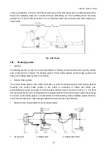
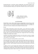
Parking brake system, or hand brake, consists of parking brake, control handle and flexible control
shaft to park vehicle for a long time. Parking brake, also called center brake, is a self-servo two-shoe
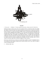
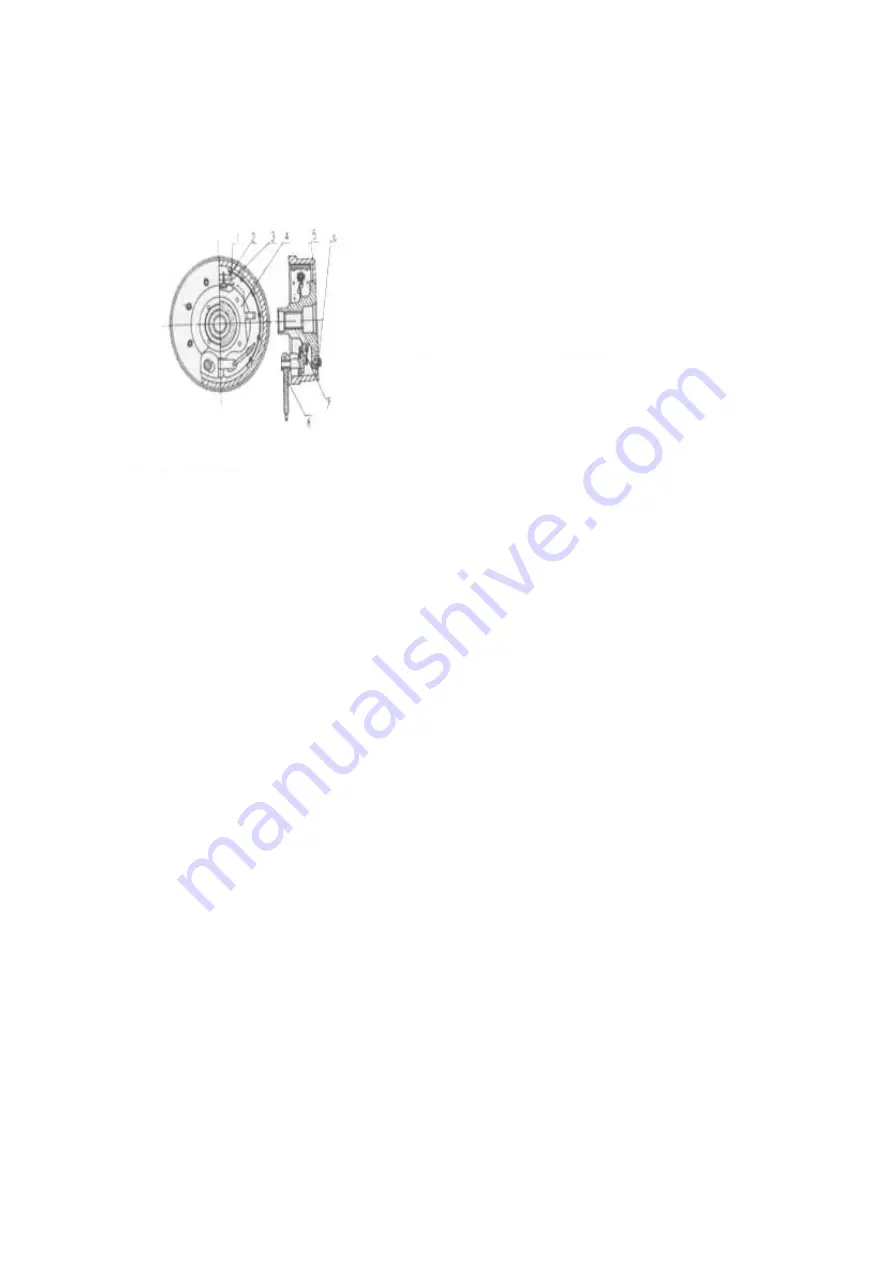
internal expanding brake and fitted to front output shaft of transmission. See Fig. 3-25 for the structure.
Fig. 3-25 Hand Brake
Parking brake is used for parking braking. During the parking braking, the driver pulls up control
handle to make the draw bar (8) swing by operating the flexible shaft, and with the swinging of the
draw bar, involute cam on the draw bar end deflects, causing both brake shoes (1) expanding to be
pressed on the inner circle of brake drum which rotates with transmission shaft.
Notices:
Common faults for parking brake are wearing of friction plate (1), crack on brake drum, wear, dragging
mark or grooving on surface, and looseness or looseness of clamping stem (7) in pin hole. Repair and
replace it when it is damaged. When friction plate is worn that it is only 0.5mm away from the head of
rivet, or it is burned or contaminated seriously (clean oil stain with gasoline generally), replace it.
Dragging mark or grooving in inner circle of brake drum is deeper than 1.5mm or worn seriously,
causing out-of-roundness, repair or replace it.
Cylindricity for inner diameter of brake drum should be no more than 0.52mm, and runout of working
surface to transmission output shaft center line should be no more than 0.12mm. Dynamic balance
value should be no more than 80g/cm.
Replace connecting pins if their fitting clearance is more than 0.2mm.
After reassembling, use a screwdriver (2) to adjust the clearance between brake shoe and brake drum
and the clearance should be within 0.3-0.5mm. When pulling control lever, effective contact area
between shoe plate and brake drum should be more than 82% to park the vehicle at a slope with
gradient no less than 8°. After the braking is released, the friction plate should separate from the brake
drum.
If adjusting rod does not meet requirement after adjustment, adjust the flexible control shaft by the
following steps: pull out split pin on flexible shaft end connected to the draw bar (8), adjust U-fork to
change the length of flexible shaft core, thus changing the turning angle of draw bar cam surface and
increasing/decreasing clearance between brake shoe and brake drum, and finally perform the fine
1. Brake 2. Adjusting rod 3. Spring
4. Seat board 5. Flange 6. Brake drum
7. Clamping stem 8. Pull rod

