Operation Manual
62
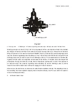
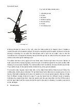
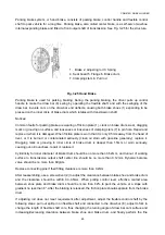
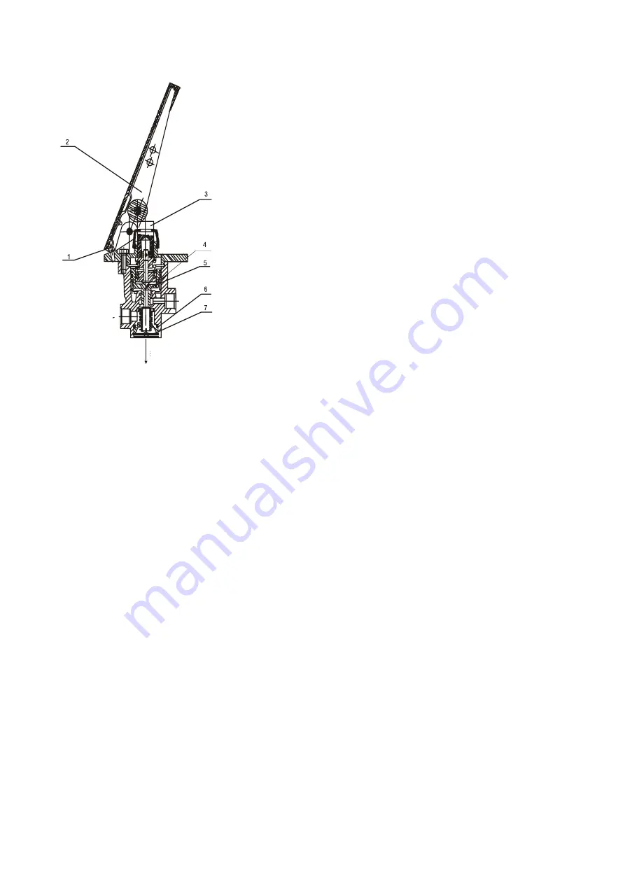
Fig. 3-23 Air brake master valve
1. Adjusting screw
2. Pedal
3. Mandril
4. Balance spring
5. Return spring
6. Piston
7. Air intake valve
Working principle: As shown in Fig. 3-23, when the brake pedal (2) is stepped down, it applies a
certain pressure to the balance spring (4) through the mandril to push the piston (6) down to close the
passage connecting the air outlet and atmosphere and to open the air intake valve so that the
compressed air is charged into braking components through the air outlet and the air pressure at air
outlet is relived through air discharge port.
The rubber dust boot at the upper end of air brake valve shall be kept intact. The inner chamber of
brake valve shall be cleaned regularly and a thin layer of oil shall be applied on the piston surface after
cleaning to ensure piston flexibility. The internal rubber drum membrane and valve shall be kept intact.
They shall be made of oil-resistant rubber instead of any other general material.
The booster pump requires clean brake fluid, so the brake fluid shall be filtered at each filling. The
oil-filling hole shall be kept unblocked. 719 synthetic brake fluid is filled into the master pump oil cup to
improve the braking reliability and reduce “air resistance” in oil circuit system pipeline. Mixture of brake
fluid of different models shall not be used. To use the brake fluid of a different model, completely
discharge the original brake fluid, clean the system with the new brake fluid, and then fill the system
with the new brake fluid. No mineral oil shall be used in the system; otherwise, the rubber components
will be damaged.
D. Booster pump:
Air outlet
Air discharge port

