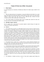
Operation Manual
44
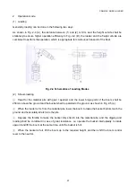
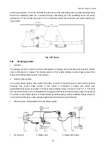
1. Engine
2. Hydraulic torque
converter
3. Transmission
4. Hand brake
5. Wheel
6.
Wheel-side
reducer
7. Differential
8. Drive axle
9. Main drive
10. Propeller shaft
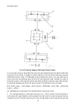
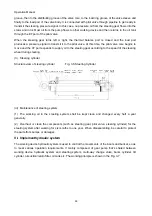
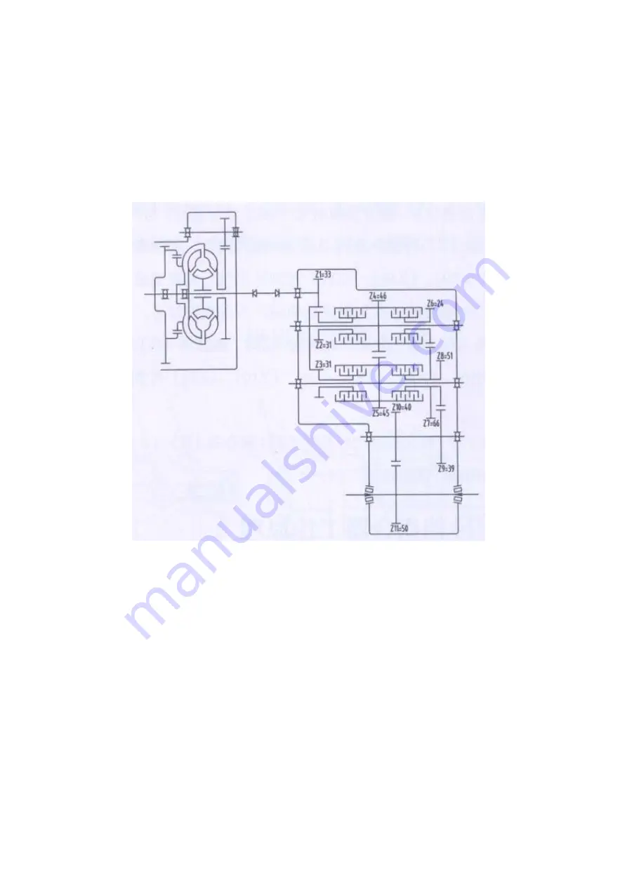
The transmission is mainly composed of transmission housing, 4 gearshift clutches (i.e. forward clutch,
reverse clutch, gear I clutch and gear II clutch), transmission control valve, oil filter as well as shaft and
gear.
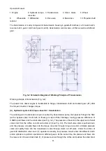
Fig. 3-2 Schematic Diagram of Working Principle of Transmission
Working principle of transmission (Fig. 3-2):
The power from diesel engine is transmitted to flange, transmission shaft and related gear (Z1) after
the torque converter changes torque.
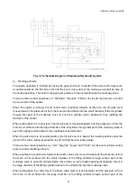
(ii) Hydraulic system of torque converter / transmission
The working oil in transmission oil pan is sucked by transmission pump, then passes through the filter
(with a bypass valve for smooth oil flowing in case of filter blockage, having pressure difference of
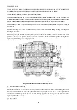
0.3MPa) and flows into the relief valve (see Fig. 3-2). The pressure oil flows into the upper end of relief
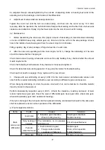
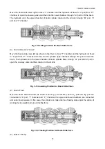
valve stem from the orifice on relief valve stem (2) (see Fig. 3-3). The relief valve stem is pushed down,
and the pressure oil partly flows into the torque converter through torque converter oil intake pressure
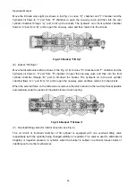
valve and partly flows into the transmission valve through clutch cut-off valve. Under the action of
gearshift distribution valve lever (4) operated manually, the pressure oil will enter into different clutch
piston cylinders to perform operations in different gears. At the same time, the pressure oil flows into
the lower end of lower slide block (7) of pressure valve through the orifice and pushes the slide block

