


7.16 Safe Brake Control (SBC)
The SBC function is defined according to EN 61800-5-2.
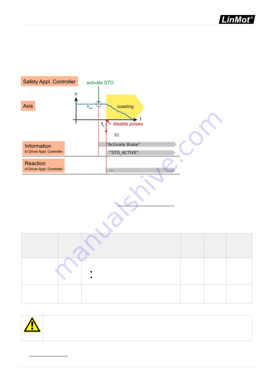
The SBC function supplies a safe output signal to control a holding brake.
On the drive, there is one output for the safe brake implemented, it is located on X50 Pin 1 (Brake+) and Pin 2 (Brake -).
The SBC can also be used with non-safe position encoders.
Figure 24: SBC
With the SBC function the monitoring of the brake controlling hardware and the presence of the brake is regularly tested.
The test checks, if the current to the brake can be turned off (the brake is in the safe state, when no current is driven).
The safe brake test (SBT) is described in chapter 7.17 - Safe Brake Test (SBT).
7.16.1 Parameters
The parameters are located under \Parameters\Safety\STO/SBC/SBT\.
Name
UPID
Type
Unit
Description
Min
Max
Typical
Brake attached
47D4h
UInt8
-
Defines if a brake is attached or not.
00h: Not Attached (Default)
01h: Attached
-
-
Not Attached
SBC STO_Delay
47D5h
UInt16
1ms
Defines the delay between brake and STO, this value is
only used if a brake is configured.
0 s
60 s
20 ms
Table 69: SBC/SBT Parameters
NOTICE
Brake Configuration
If the brake is attached on X50, also the non-safe configuration under "Brake Config", UPIDs 1716h to
1719h, 171Bh and 171Ch have to be set accordingly.
If the state of the brake output shall be displayed with the safe digital output, the configuration must be set accordingly,
see 7.13.2 - Parameters
2S Drive Systems / 0185-1174_E_1V1_SM_C1251-2S / NTI AG
0185-1174_E_1V1_SM_C1251-2S / 2021-11-26 16:43 (Rev. 12500)
Page 100 of 150