Alignment Menu
Use the alignment menu to align the image on the page for cyan, yellow, and magenta. The black image should be
aligned using REGISTRATION before the individual colors are aligned.
Warning—Potential Damage:
Read the instructions for the alignment carefully.
Setting alignment for color
1
From the Diagnostics menu, touch
Alignment Menu
.
2
Select
CYAN
,
YELLOW
, or
MAGENTA
.
3
Touch
Quick Test
. You may need to scroll to the next page.
A two-page instruction sheet prints.
The printer prints the test page from the default paper source, however if the default source only supports
envelopes, then the page prints from Tray 1. Print on A4 or letter paper for the best results.
4
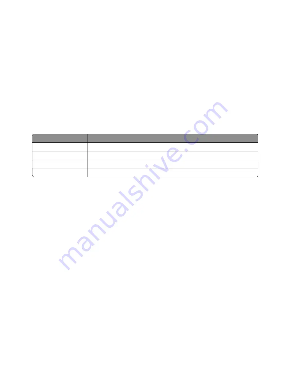
Determine which settings to change and follow the instructions on the printed sheets to determine the adjustment.
Description
Range
Top Margin
-128 to +127
Left Margin
-2500 to +2500 (-1000 to +1000 for Yellow)
Right Margin
-2500 to +2500 (-1000 to +1000 for Yellow)
Linearity
Linearity has a separate Quick Test sheet and adjustment instructions.
5
Touch (
-
) to decrease the value or (
+
) to increase the value. After the value appears, touch to save the value or
Back
to cancel.
6
Reprint the Quick Test to evaluate the changes. Continue until each adjustment is correct.
7
Repeat steps 4 through 6 as needed.
8
Continue until all three colors are aligned. A separate Quick Test prints for each color.
9
Touch
Back
to exit the Alignment Menu
Scanner calibration
Scanner calibration
This diagnostic test is used to calibrate both the Black and white values for the ADF and the flatbed. The following values
can be adjusted using this menu item:
•
Flatbed Black – Values are -10 to 10. The default value is 0.
•
ADF Front Black – Values are -10 to 10. The default value is 0.
•
ADF Back Black – Values are -10 to 10. The default value is 0.
•
Flatbed White – Values are -10 to 10. The default value is 0.
•
ADF Front White – Values are -10 to 10. The default value is 0.
•
ADF Back White – Values are -10 to 10. The default value is 0.
7527
Service menus
168
Содержание CX310dn
Страница 24: ...7527 24 ...
Страница 154: ...7527 154 ...
Страница 187: ...D ADF cover open E Flatbed cover open F Paperfeed sensor 7527 Service menus 187 ...
Страница 224: ...3 Remove the four screws A securing the right scanner cover to the flatbed unit 7527 Repair information 224 ...
Страница 227: ...5 Disconnect the belt C 6 Disconnect the fan and remove 7527 Repair information 227 ...
Страница 311: ...Component locations Controller boards CX310 models 7527 Component locations 311 ...
Страница 312: ...CX410 models 7527 Component locations 312 ...
Страница 313: ...CX510 models 7527 Component locations 313 ...
Страница 318: ...7527 318 ...
Страница 325: ...7527 325 ...
Страница 327: ...Assembly 1 Covers 7527 Parts catalog 327 ...
Страница 329: ...Assembly 2 Scanner 7527 Parts catalog 329 ...
Страница 331: ...Assembly 3 Paperpath 7527 Parts catalog 331 ...
Страница 334: ...7527 Parts catalog 334 ...
Страница 335: ...Assembly 4 Operator panels 7527 Parts catalog 335 ...
Страница 338: ...7527 Parts catalog 338 ...
Страница 339: ...Assembly 5 Electronics 7527 Parts catalog 339 ...
Страница 342: ...7527 Parts catalog 342 ...
Страница 343: ...Assembly 6 Cables and sensors 7527 Parts catalog 343 ...
Страница 345: ...Assembly 7 Media drawers and trays 7527 Parts catalog 345 ...
Страница 358: ...7527 358 ...
Страница 372: ...7527 372 ...
Страница 386: ...7527 Part number index 386 ...
Страница 392: ...7527 Part name index 392 ...


