ELECTRICAL SYSTEM
4-7
Replacing the Seat Switch
1.
Set the key switch to OFF, remove the key from the
key switch and place in a secure area.
2.
Apply the parking brake, perform a Lock Out/Tag Out
procedure, disconnect battery and block all wheels.
3.
Remove the hardware securing the front portion of
the seat slide rails to the cover. Then loosen the back
two sets of hardware.
4.
Raise the front of the seat up to expose the switch
and cable mounting.
5.
Have a helper disconnect the switch cable from the
main harness, then unscrew the switch assembly.
6.
Install the new switch and cable by performing the
preceding steps in reverse order.
7.
Before placing the truck back into operation, test it to
be sure the switch functions properly. See “Check
Driver’s Seat Switch” on page 4-6.
Truck Lighting
Trucks equipped with optional lighting, flashing or spot
lights may contain replaceable bulbs, or the housing may
be replaced as a whole. Lighting replacement varies
according to the manufacturer.
Headlights
These lights have non-replaceable LED elements and
are replaced as an entire unit.
Brake and Tail Lights
1.
Set the key switch to OFF and remove the key.
2.
Apply the parking brake and disconnect the battery.
3. The complete LED light assembly must be replaced
to repair a faulty light assembly.
4.
Pull off the complete LED light assembly. Exercise
care to avoid breaking the LED assembly.
5.
Disconnect the wire connector and remove the
bracket that is attached to the overhead guard.
6.
If shielding or guard covers are involved, make
certain that the guard is replaced after the repair.
7.
Reassemble in reverse order.
Back Up Alarms
1.
Set the key switch to OFF and remove the key.
2.
Disconnect the battery.
3. To replace the alarm assembly, disconnect the wire
connector and remove the mounting hardware
holding the alarm to the overhead guard.
4.
Reassemble in reverse order.
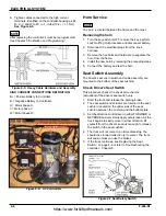
Overhead Guard, Lighting and Alarms
Trucks equipped with optional LED flood / headlights, tail
and stop lights, flashing or spot lights (strobe lights), etc.
do not contain replaceable bulbs. Bulb replacement must
be done as a complete assembly. See Figure 4-8.
Figure 4-8 Overhead Guard
Side Shift Circuit Maintenance
The following information is provided for authorized ser-
vice facilities ONLY.
Perform maintenance on the side shift circuit as required
by the Hourly Checklists.
Check the hydraulic system pressure at the control valve
fitting. Refer to the truck service manual for details on
measuring hydraulic system pressure, see page 3-3.
System pressure must not exceed 3000 psi (206 bar).
CAUTION
• Before you remove any hoses or tubes,
relieve hydraulic system pressure. With the
truck off, manipulate the truck auxiliary
control valve(s) several times in both
directions.
• Check for hydraulic fluid leaks using a piece
of cardboard or wood. Do not use your hands.
• Remember to wear safety glasses.
https://www.forkliftpdfmanuals.com/
Содержание Drexel SLT30 AC
Страница 2: ...https www forkliftpdfmanuals com...
Страница 36: ...2 16 F 459 R1 TIRES BRAKES AND DRIVETRAIN Table provided for general use NOTES https www forkliftpdfmanuals com...
Страница 69: ...DREXEL SLT30 35 AC CALIBRATION PROGRAMMING 5 17 https www forkliftpdfmanuals com...
Страница 70: ...5 18 F 459 R1 DREXEL SLT30 35 AC CALIBRATION PROGRAMMING https www forkliftpdfmanuals com...


