Shini SDL-U Series Скачать руководство пользователя страница 1


SDL-U-HD 

Series


Heatless Dehumidifying Compact Dryer 


Date: Nov. 2014 

Version: Ver.B (English) 


Содержание SDL-U Series

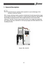
Страница 1: ...SDL U HD Series Heatless Dehumidifying Compact Dryer Date Nov 2014 Version Ver B English...

Страница 2: ......

Страница 3: ...2 1 System structure 18 2 2 2 Assembly Drawing 19 2 2 3 Parts List 20 2 2 4 Filter Pressure Regulating Valve Drawing 23 2 2 5 Heater 24 2 3 Electrical Diagram 25 2 3 1 Electrical Circuit 25 2 3 2 Main...

Страница 4: ...rouble shooting 52 6 Maintenance and Repair 53 6 1 Filter Pressure Regulating Valve 53 6 1 1 Filter Pressure Regulating Valve Drawing 53 6 1 2 Filter Pressure Regulating Valve Operation steps 54 6 2 A...

Страница 5: ...cifications 10 Table 2 1 Parts List SDL 20U 120U HD 20 Table 2 2 Parts List SDL 160U 450U HD 21 Table 2 3 Parts List SDL 600U 1200U HD 22 Table 2 4 Electrical Circuit 25 Table 2 5 Electrical Component...

Страница 6: ...450U HD 29 Picture 2 9 Electrical Components Layout SDL 20U 450U HD 30 Picture 2 10 Main electrical circuit SDL 600U 1200U HD 38 Picture 2 11 Control circuit 1 SDL 600U 1200U HD 39 Picture 2 12 Contr...

Страница 7: ...air drying and two stage conveying functions into a compact unit It is particularly suitable for using with the big tonnage moulding machines when height restriction is concerned at the workshop The...

Страница 8: ...nless steel to avoid contamination Full functional alarming system can immediately show faults Closed loop conveying device eliminates the possibility of moisture reabsorption during dried material co...

Страница 9: ...ny modifications of the machine must be approved by SHINI in order to avoid personal injury and damage to machine We shall not be liable for any damage caused by unauthorized change of the machine Our...

Страница 10: ...300 450 600 750 900 1200 Process Heater kW 2 2 3 3 9 3 9 6 6 12 12 18 18 24 24 Conveying Blower kW 50 60Hz 1 5 1 8 1 5 1 8 1 5 1 8 1 5 1 8 1 5 1 8 1 5 1 8 1 5 1 8 1 5 1 8 1 5 1 8 1 5 1 8 2 4 3 0 2 4 3...

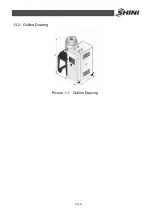
Страница 11: ...11 63 1 3 2 Outline Drawing Picture 1 1 Outline Drawing...

Страница 12: ...ops Clean the filter about once a week 4 Clear up inside and outside of the blower regularly If there are too much dirts accumulated on the blower the function of the blower will be affected such as t...

Страница 13: ...the Machine Transportation 1 SDL U HD series are packed in crates or plywood cases with wooden pallet at the bottom suitable for quick positioning by fork lift 2 After unpacked castors equipped on th...

Страница 14: ...l shock 3 If it has been dropped or damaged until it is checked or fixed by a qualified serviceman 4 This equipment works normally in the environment with altitude within 3 000m 5 At least a clearance...

Страница 15: ...Any incidents beyond human reasonable controls which include man made vicious or deliberate damages or abnormal power and machine faults caused by irresistible natural disasters including fire flood s...

Страница 16: ...l be sucked into hopper Due to the filter block of hopper materials will be accumulated in hopper and the air is expelled from air outlet Double stage conveying is mainly accomplished by shifting thre...

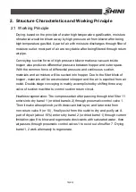
Страница 17: ...17 63 Picture 2 1 Working Principle...

Страница 18: ...hopper 3 Heating box 4 Drying blower 5 Heatless regeneration air dryer 6 Rack 7 Shut off valve suction box 8 Three way valve 9 Conveying blower 10 Filter pressure regulating valve 11 Castor 12 Filter...

Страница 19: ...19 63 2 2 2 Assembly Drawing Remarks Please refer to material list 2 2 3 for specific explanation of the Arabic numbers in parts drawing Picture 2 3 Assembly Drawing...

Страница 20: ...blower BM30042000050 BM30042000050 BM30042000050 BM30042000050 10 3 castor YW03000300200 YW03000300200 YW03000300200 YW03000300200 11 Heatless regeneration dryer BY90106600050 BY90106600050 BY9010660...

Страница 21: ...r BM30042000050 BM30042000050 BM30042000050 BM30042000050 10 3 castor YW03000300200 YW03000300200 YW03000300200 YW03000300200 11 Heatless regeneration dryer BY90206600050 BY90035600050 BY90035600050 Y...

Страница 22: ...0000 9 Conveying blower BM30042000050 10 3 castor YW03000400200 11 Heatless regeneration dryer YE90112100000 12 Shut off valve suction box BY10163800250 13 Pipe heater BH70601800250 14 Drying blower B...

Страница 23: ...23 63 2 2 4 Filter Pressure Regulating Valve Drawing Parts list 1 Pressure adjusting knob 2 Pressure gauge 3 Cup 4 Water outlet Picture 2 4 Filter Pressure Regulating Valve Drawing...

Страница 24: ...24 63 2 2 5 Heater Parts Name 1 Heating chamber s outer housing 2 Hot air tube 3 Pipe heater 4 Heating chamber cover Picture 2 5 Heater...

Страница 25: ...0 0 63 1 0 65 0 25 0 65 1 0 3 2 5 SDL 600U HD 6 0 40 32 1 0 0 8 1 25 0 94 0 55 0 94 1 0 3 2 5 SDL 750U HD 6 0 40 32 1 0 0 8 1 25 0 94 0 55 0 94 1 0 3 2 5 SDL 900U HD 10 0 63 50 1 0 0 8 1 25 0 94 0 55...

Страница 26: ...Breaker Drying diameter motor Load drying windmill Dry motor load set Drying motor power Current dry motor Suction diameter windmill Suction of the motor turbine load Suction motor load is set Suction...

Страница 27: ...27 63 2 3 2 Main Circuit SDL 20U 450U HD Picture 2 6 Main Circuit SDL 20U 450U HD...

Страница 28: ...28 63 2 3 3 Control Circuit SDL 20U 450U HD Picture 2 7 Control Circuit 1 SDL 20U 450U HD...

Страница 29: ...29 63 Picture 2 8 Control Circuit 2 SDL 20U 450U HD...

Страница 30: ...30 63 2 3 4 Electrical components layout SDL 20U 450U HD Picture 2 9 Electrical Components Layout SDL 20U 450U HD...

Страница 31: ...000000 17 S7 Thermocouple K BE90802000050 18 Y1 Y2 Y3 Magnetic valve 230VAC 50 60Hz YE32051800300 19 Z EMI 250VAC 1A YE73011100000 20 PCB 01 PCB STC43 44 YE80001500000 21 PCB 02 PCB SFD 102 YE80010200...

Страница 32: ...e K BE90802000050 18 Y1 Y2 Y3 Magnetic valve 230VAC 50 60Hz YE32051800300 19 Z EMI 250VAC 1A YE73011100000 20 PCB 01 PCB STC43 44 YE80001500000 21 PCB 02 PCB SFD 102 YE80010200000 22 PCB 03 PCB YE8051...

Страница 33: ...mocouple K BE90802000050 18 Y1 Y2 Y3 Magnetic valve 230VAC 50 60Hz YE32051800300 19 Z EMI 250VAC 1A YE73011100000 20 PCB 01 PCB STC43 44 YE80001500000 21 PCB 02 PCB SFD 102 YE80010200000 22 PCB 03 PCB...

Страница 34: ...le K BE90802000050 18 Y1 Y2 Y3 Magnetic valve 230VAC 50 60Hz YE32051800300 19 Z EMI 250VAC 1A YE73011100000 20 PCB 01 PCB STC43 44 YE80001500000 21 PCB 02 PCB SFD 102 YE80010200000 22 PCB 03 PCB YE805...

Страница 35: ...E90802000050 18 Y1 Y2 Y3 Magnetic valve 230VAC 50 60Hz YE32051800300 19 Z EMI 250VAC 1A YE73011100000 20 PCB 01 PCB STC43 44 YE80001500000 21 PCB 02 PCB SFD 102 YE80010200000 22 PCB 03 PCB YE805125001...

Страница 36: ...0VDC YE15143900000 16 S5 Overheat protector 250V 5 4 A YE21503000000 17 S7 Thermocouple K BE90802000050 18 Y1 Y2 Y3 Magnetic valve 230VAC 50 60Hz YE32051800300 19 Z EMI 250VAC 1A YE73011100000 20 PCB...

Страница 37: ...Overheat protector 250V 5 4 A YE21503000000 17 S7 Thermocouple K BE90802000050 18 Y1 Y2 Y3 Magnetic valve 230VAC 50 60Hz YE32051800300 19 Z EMI 250VAC 1A YE73011100000 20 PCB 01 PCB STC43 44 YE800015...

Страница 38: ...38 63 Picture 2 10 Main electrical circuit SDL 600U 1200U HD...

Страница 39: ...39 63 2 3 7 Control circuit SDL 600U 1200U HD Picture 2 11 Control circuit 1 SDL 600U 1200U HD...

Страница 40: ...40 63 Picture 2 12 Control circuit 1 SDL 600U 1200U HD...

Страница 41: ...41 63 2 3 8 Electrical components layout SDL 600U 1200U HD Picture 2 13 Electrical components layout SDL 600U 1200U HD...

Страница 42: ...2000050 18 Y1 Y2 Y3 Magnetic valve 230VAC 50 60Hz YE32051800300 19 Z EMI 250VAC 1A YE73011100000 20 PCB 01 PCB STC43 44 YE80001500000 21 PCB 02 PCB SFD 102 YE80010200000 22 PCB 03 PCB YE80512500100 23...

Страница 43: ...0VDC YE15143900000 16 S5 Overheat protector 250V 5 4 A YE21503000000 17 S7 Thermocouple K BE90802000050 18 Y1 Y2 Y3 Magnetic valve 230VAC 50 60Hz YE32051800300 19 Z EMI 250VAC 1A YE73011100000 20 PCB...

Страница 44: ...00000 16 S5 Overheat protector 250V 5 4 A YE21503000000 17 S7 Thermocouple K BE90802000050 18 Y1 Y2 Y3 Magnetic valve 230VAC 50 60Hz YE32051800300 19 Z EMI 250VAC 1A YE73011100000 20 PCB 01 PCB STC43...

Страница 45: ...900000 16 S5 Overheat protector 250V 5 4 A YE21503000000 17 S7 Thermocouple K BE90802000050 18 Y1 Y2 Y3 Magnetic valve 230VAC 50 60Hz YE32051800300 19 Z EMI 250VAC 1A YE73011100000 20 PCB 01 PCB STC43...

Страница 46: ...ontrol panel 4 The power cable connection terminals should be tightened securely 5 The machine requires a 3 phase 4 wire power source connect the power lead L1 L2 L3 to the live wires and the earth PE...

Страница 47: ...the combustible distance 3 4 Pipe Heaters 1 Put the heating pipe into the heating chamber 2 Fix the heating chamber on the machine housing Picture 3 3 Pipe Heaters Warning High temperature take care o...

Страница 48: ...chine frame Picture 3 4 Drying Blower 3 5 2 Conveying Blower 1 Fix inlet outlet flange of blower and tighten 4 screws securely 2 Connect the blower with electrical power source 3 Install the blower on...

Страница 49: ...5 4 Filter Pressure Regulating Valve 1 Switch on the air source 2 Pull the black pressure adjusting knob 1 upward and rotate it observe the pressure gauge 2 generally a 0 5 Mpa pressure is advisable...

Страница 50: ...50 63 3 5 6 Filter 1 Fix the filter on filter support 2 Install the filter and its support on the rear plate with screws 3 Connect to the compressed air tube Picture 3 8 Filter...

Страница 51: ...SET and key to set the temperature Then confirm the temperature setting by pressing ENTER key 4 2 Operation of conveying system 1 Press once to set the suction time of the hopper 1 Press twice to set...

Страница 52: ...off load 1 Check reason and reset 2 Connector is not working 2 Check it is burnt out or not Motor does not run 3 Power source lack of phase or motor is burnt out 3 Check and replace 1 LED sensor or mi...

Страница 53: ...53 63 6 Maintenance and Repair 6 1 Filter Pressure Regulating Valve 6 1 1 Filter Pressure Regulating Valve Drawing...

Страница 54: ...ob 1 6 2 Air Filters Please periodically clean the dust on the air filters once per week Cleaning steps 1 Take out the air filter carefully 2 Blow off the dust on the air filter screen and the cover w...

Страница 55: ...wall type GXW series is a heatless regeneration adsorption type dryer which dry the compressed air according to Pressure Swing Adsorption PSA principle Adopt the compact design and high reliability o...

Страница 56: ...e installed in a clean air environment and at a temperature of 4 52 for the dryer can be damaged in frozen temperature 2 Install 4 expansion bolts of 6 at an appropriate height on the wall and connect...

Страница 57: ...ine at a freezing temperature 3 Regularly draw off the water in the front filter manually or install an automatic drainage device to prevent the water from entering the dry tower and caused damage 4 I...

Страница 58: ...Hz 12W Installation method integrated Installation site Indoor wall hanging style 6 4 5 Maintenance 6 4 5 1 Adjustment and Monitoring No need of on site adjustment and lubricant 1 Regularly check the...

Страница 59: ...mperature large outlet flow the dryer continues to work after the outlet valve shut down for several hours regenerate overwet hopper etc 6 4 5 7 Oil Pollution Oil pollution will cause complete failure...

Страница 60: ...e filter cup shield 4 Take down the filter cup 5 Firmly grasp the filter element and unscrew the screw The hanger bolt and filter element is integrated 6 Take out the old filter element and put it awa...

Страница 61: ...ce it 4 Increase the regeneration air flow 5 Increase the inlet pressure 6 Replace the O ring use the glue or install a new one 7 Clean repair or replace the shuttle valve 8 Repair or replace the magn...

Страница 62: ...ed Electrical Installation Voltage V Hz Fuse melt current 1 Phase A 3 Phase A Check phase sequence of the power supply 6 5 3 Daily Checking Check power supply wires Check the start stop function 6 5 4...

Страница 63: ...63 63 Check if there are damages of heat resistant hoses Check the pipe heaters Check process blower and blower fans...

Отзывы: