ELECTRICAL SYSTEM
4-5
Battery Removal
CAUTION
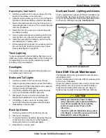
Rollout Battery Removal - optional
1.
Remove the safety retainer bar, activating the safety
switch.
2.
Position battery roll out stand next to the truck and
align the stand with the path of the battery.
3.
Roll and secure the battery onto the stand.
Battery Installation
1.
Change and charge batteries in accordance with
ANSI/NFPA 505.
2.
Check to be sure the key is off.
3.
Open the right hand door.
4.
If using a rollout stand, position the battery stand
next to the truck. Align stand with battery
compartment. Battery roller stand should be the
same height as the truck.
5.
Push battery into the truck’s battery compartment or
lower if using a hoist.
6.
Install battery retainer safety bar or the truck will not
operate.
7.
Connect the battery.
Electrical Controls and Levers
Joystick
NOTE
The directional control lever (forward-neutral-reverse) is
located on the joystick. The joystick is replaced as a
complete unit only.
Replacing the Joystick
1.
Set the key switch to OFF, remove the key from the
key switch and place in a secure area
2.
Set the key switch to OFF, remove the key from the
key switch and place in a secure area.
3.
Perform a Lock Out/Tag Out procedure and
disconnect the battery.
4.
Make sure all the other wheels are securely blocked
so that the truck cannot move.
5.
Remove the boot that covers the joystick fasteners.
6.
Remove the four screws that hold down the joystick.
7.
Gently lift up on the joystick to expose the wiring
harness.
8.
Unhook wiring harness.
9.
Replace in reverse order.
10. Test for proper operation.
Check the Return-to-Neutral
1.
Sit in the driver’s seat, and turn the key switch ON.
2.
Set the direction control lever to FORWARD.
3.
Slowly move the truck forward, then stop by using the
service brake.
4. Turn the key switch OFF, then back on again.
5.
Press on the accelerator pedal.
6. The truck must not move.
7.
If the truck does not move, take your foot off the
accelerator pedal. Place the directional control lever
in NEUTRAL then back to FORWARD again.
8.
Slowly push on the accelerator pedal. The truck
should move forward. If it does not move, Refer to
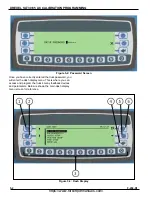
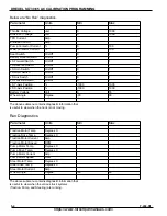
Programming Troubleshooting Chart and the dash
display.
9.
Repeat preceding Steps through, but instead of
turning the key switch OFF in Step, lift yourself from
the driver’s seat to allow the switch interlock to
release. The truck must react as stated in Steps 5
through 8.
Replacing a Complete Control Panel
1.
Set the key switch to OFF, remove the key from the
key switch and place in a secure area.
2.
Apply the parking brake, perform a Lock Out/Tag Out
procedure and disconnect the battery.
3.
Make sure all the other wheels are securely blocked
so that the truck cannot move. See page 1-5.
4.
Remove the control compartment cover.
5.
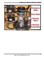
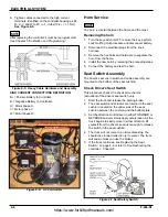
Mark and remove all cables connected to high
current terminals of the panel and disconnect the
main harness. See Figure 4-6.
6.
Remove mounting hardware that secures the
assembly to the truck and remove the panel or single
component from the truck.
7.
Reassemble in reverse order. All cables installed on
the motor controllers must use all the required
Landoll approved fasteners and be in the correct
assembled order. See Figure 4-5. Refer to the
SLT30/35 AC Parts Manual for replacement parts.
Don’t allow metallic objects to be on top or near
the battery. A short could cause an electrical arc
and personal injury may result. When moving the
battery, keep the top of the battery covered with
an insulator, such as a piece of plywood or tarp.
https://www.forkliftpdfmanuals.com/
Содержание Drexel SLT30 AC
Страница 2: ...https www forkliftpdfmanuals com...
Страница 36: ...2 16 F 459 R1 TIRES BRAKES AND DRIVETRAIN Table provided for general use NOTES https www forkliftpdfmanuals com...
Страница 69: ...DREXEL SLT30 35 AC CALIBRATION PROGRAMMING 5 17 https www forkliftpdfmanuals com...
Страница 70: ...5 18 F 459 R1 DREXEL SLT30 35 AC CALIBRATION PROGRAMMING https www forkliftpdfmanuals com...


