3-4
F-459-R1
HYDRAULIC OIL, MOTORS, PUMPS AND CYLINDERS
Hydraulic Pump Service
NOTE
The hydraulic lift pump used on the SLT30/35 AC has no
serviceable parts and is repaired by replacement only.
When replacing the lift pump, make sure that the
hydraulic oil is clean and that the hydraulic system has a
new clean filter. See “Changing Hydraulic Oil” and
“Changing Hydraulic Filter” on page 3-2.
Replacing the Hydraulic Pump and
Motor
NOTE
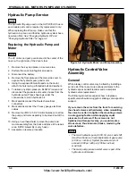
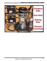
The AC motor and pump are located in the center of the
truck on the right side of the driver’s feet.
1.
Remove the key and place in a secure area.
2.
Perform the Lock Out/Tag Out procedure.
3.
Disconnect the battery.
4.
Remove the floor plate and the main side cover to
expose the hydraulic pump and motor.
5.
Using the exposed female threads on the motor,
attach the hoist using a threaded bolt and washers.
6. To relieve any static pressure, SLOWLY loosen and
disconnect the pressure and suction hoses from the
hydraulic pump. Place shop rags under the
connections to catch hydraulic oil.
7.
Mark and disconnect the Deutsch electrical
connectors.
8.
Mark and disconnect the 3 heavy gauge electrical
cables.
9.
Remove four M8-1.25 X 20 motor fasteners, to allow
the pump and motor assembly to be moved out of the
frame.
10. Using an overhead hoist, remove the pump and
motor assembly from the truck and place it the repair
area. NOTE: Assembly is very heavy.
11. Assemble in reverse procedure.
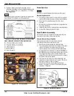
Figure 3-4: Hydraulic Motor and Pump Assembly
Hydraulic Control Valve
Assembly
General
While a leaky control valve may be fixed by installing a
service kit, if there are more serious problems to the
hydraulic spool, Landoll recommends a complete
hydraulic valve replacement.
The following procedure explains how to replace a
specific valve should a sluggish or sticking valve spool be
suspect.
If you remove the valve from the truck for servicing
(hex head screws and hardware), when reinstalling
the valve be certain to tighten the mounting screws
in a staggering fashion while applying equal
pressure to all screws. If the screws are not
tightened and torqued evenly, you could create a
stress crack, thus internal oil leaks, rendering the
valve defective.
NOTE
• The main hydraulic pump for lift, tilt, pivot, and shift
(mast functions) is a fixed displacement gear pump
(2.008 cu. inch/rev). System pressure must not
exceed 3,000 psi, ±65 psi (206 bar, ±4 bar)
maximum.
• The main pump pressure relief valve is part of the
hydraulic control valve.
https://www.forkliftpdfmanuals.com/
Содержание Drexel SLT30 AC
Страница 2: ...https www forkliftpdfmanuals com...
Страница 36: ...2 16 F 459 R1 TIRES BRAKES AND DRIVETRAIN Table provided for general use NOTES https www forkliftpdfmanuals com...
Страница 69: ...DREXEL SLT30 35 AC CALIBRATION PROGRAMMING 5 17 https www forkliftpdfmanuals com...
Страница 70: ...5 18 F 459 R1 DREXEL SLT30 35 AC CALIBRATION PROGRAMMING https www forkliftpdfmanuals com...


