TIRES, BRAKES AND DRIVETRAIN
2-7
5.
Loosen one clamp hold-down screw and remove the
other screw to allow the clamp to drop down making
it easier to remove the front and rear return springs.
6.
Unhook and remove both return springs.
7.
Press in on the hold-down spring and pop it to one
side (opposite of where hook is attached) to free the
spring hook from the rear of the brake backing plate.
This will require some force to compress the spring to
pop it free.
8.
Remove both hold down screws and the hold down
clamp. Carefully separate the front and rear shoes
from the wheel cylinder.
9.
Clean the area and check the wheel cylinder for
leaks. Pull back on the bottom portion of the rubber
boot on both sides of the cylinder. If it is not dry, see
“Repairing Brake Wheel Cylinders,” page 2-7.
NOTE
Check the brake lines for cracking, splits, or any apparent
weakness - replace as needed.
10. SPARINGLY lubricate the brake shoe contact areas
of the backing plate with high temperature grease.
Install the new brake shoes and install the brake
drum (two outer hex head screws and hardware). Do
not allow any grease to come on contact with braking
area of the shoe. Torque the screws to specifications
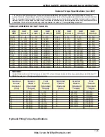
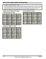
shown on page 1-12 on the “General Torque
Specification” chart.
11. Install the new brake shoes by following the above
instruction in reverse order. Be sure that all springs
are properly hooked at both ends and that they
hold-down clamp screws are tight.
12. Wiggle the brake assembly to ensure that the shoes
are centered on the backing plate.
13. Reinstall wheel assembly by following steps 19-23 on
“Load Wheel Bearing Maintenance” on page 2-3.
14. Pump the brakes several times to seat the new brake
shoes.
15. Using the brake pedal, make a few normal stops in
forward and reverse to allow the brakes to further
seat themselves. DO NOT lock the brakes which
could cause flat spots.
Repairing Brake Wheel Cylinders
NOTE
The wheel cylinder, if it freezes-up or shows signs of
leakage, must be replaced before returning the truck to
operation.
1.
Set the key switch of OFF and place the key in a
secure place.
2.
Initiate a Lock Out/Tag Out procedure.
3.
Raise the side of the truck being serviced.
4.
Remove the wheel. See “Replacing Brake Drum
5.
Remove the brake shoes. See “Changing Brake
Shoes”, on page 2-6.
6.
Using a flare-nut wrench, disconnect the brake fluid
inlet line from the wheel cylinder. Have shop rags
available to manage spills. See Figure 2-5.
7.
Do not pull the brake line away from the cylinder.
Plug the end to reduce fluid loss and contamination.
8.
Remove the two bolts holding the cylinder to the
backing plate.
9.
Install the new cylinder and tighten fasteners to the
specified torque as shown in “General Torque
Specifications” on page 1-12.
10. Connect the brake inlet line and install the brake
shoe assembly and drum. To avoid stripping the
brass threads, do not overtighten the brake line
fittings.
11. Reinstall the components in reverse order.
12. Bleed the brakes. See “Bleeding Brakes” on
NOTE
When replacing a brake assembly, a wheel cylinder or a
master cylinder, it is advisable to purge and replace the
entire brake system of old, possibly contaminated fluid.
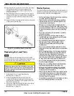
Figure 2-5 Wheel Cylinder Repair
https://www.forkliftpdfmanuals.com/
Содержание Drexel SLT30 AC
Страница 2: ...https www forkliftpdfmanuals com...
Страница 36: ...2 16 F 459 R1 TIRES BRAKES AND DRIVETRAIN Table provided for general use NOTES https www forkliftpdfmanuals com...
Страница 69: ...DREXEL SLT30 35 AC CALIBRATION PROGRAMMING 5 17 https www forkliftpdfmanuals com...
Страница 70: ...5 18 F 459 R1 DREXEL SLT30 35 AC CALIBRATION PROGRAMMING https www forkliftpdfmanuals com...

