Page 30
Function testing / setting of components
After start-up always test the equipment for correct function!
In the case of function error, in spite of correcting the setting, see page 42 "Causes and remedying of
faults”.
For function testing or setting, in the case of some components the cabinet door must be open and the conn-
necting block cover plate (
14
) unscrewed.
The inspections or settings shall partly be carried out when the equipment is on.
Deadly risk!
Do not operate the equipment with damp hands!
Take caution with live components!
Risk of injury!
Take caution with heated components!
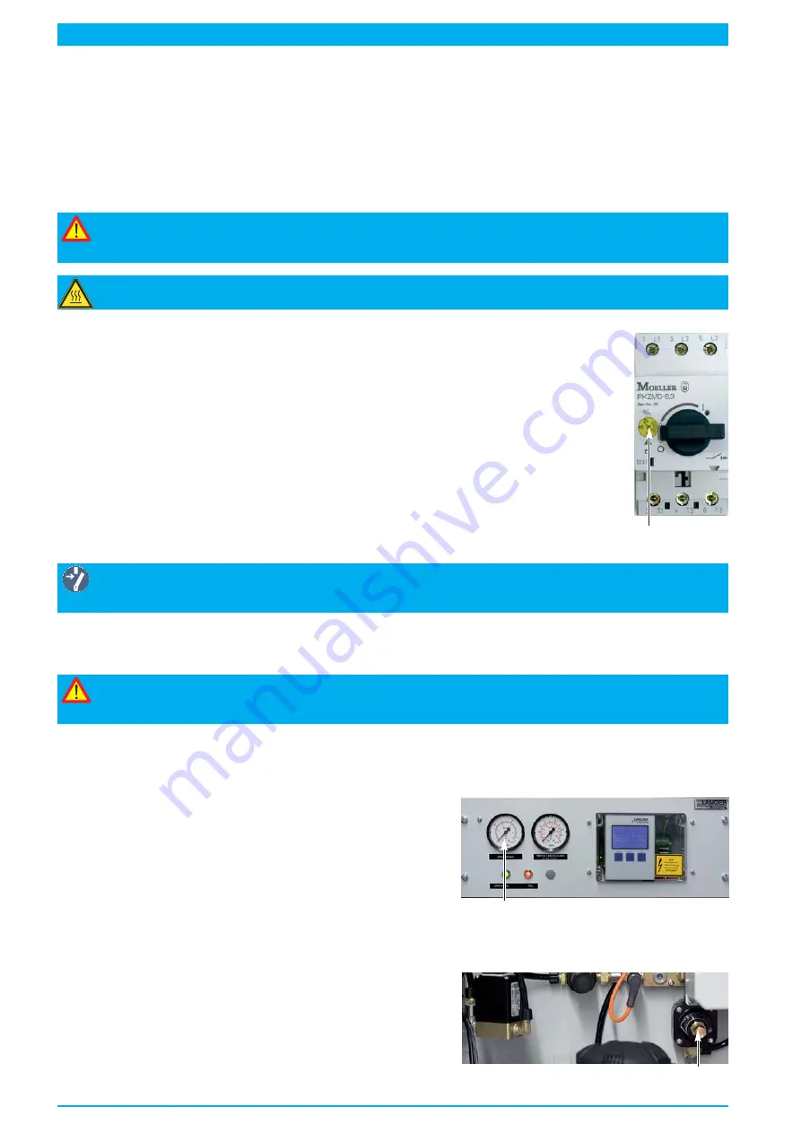
Check and set reference value motor protective switch back-up fuse
Check setting
Reference value of setting screw (
70
):
RTS 1000 with one compressor: 230 V, 50 Hz: approx. 2,4 A.
70
Change setting
Deadly risk!
Switch off operating voltage,
Unscrew or disconnect back-up fuse!
• Then with a small screw driver turn the setting screw (
70
) approximately to the setting indicated above.
• Switch on operating voltage again.
Hint!
The motor protective switch must be set approx. 0.3 A above power consumption of the com-
pressor motor (6) (see compressor name plate).
Check and set cable pressure (pressure reducer)
Setpoint value cable pressure
• is set according to the customer order.
Check cable pressure
• Switch on operating voltage.
• Close
shut-off valve (6)
.
•
Manometer "cable pressure" (
16
) must display
16
the required cable pressure.
otherwise :
Set cable pressure to the value in keeping with the order
• Operating voltage is already switched on.
•
shut-off valve (6)
is closed.
• Turn the setting screw of pressure reducer (
32
) with screw
driver until the manometer "cable pressure" (
16
) displays the
cable pressure according to the order.
• Open
shut-off valve (6)
.
32
Содержание RTS 1000
Страница 15: ...Page 15 39 35 37 36 36 23 42 28 27 24 6 33 38 40 41 32 22 29 25 8...
Страница 21: ...Page 21...
Страница 47: ...Page 47 7 16 14 15 15 18 17 13 20 24 8 23 10 6 9 4 22 21 19 8...
Страница 51: ...Page 51 Pneumatics diagram Nr 074891 000...
Страница 53: ...Page 53 Circuit diagram Nr 074880 000...
Страница 55: ...Wiring diagram Nr 074881 000 Page 55...


