Page 5
Scope of supply
• Pressurization system RTS 1000D, consisting of
- 1 solid metal cabinet with the following mounting parts:
- 1 compressor
- 1 air storage tank
- 1 air dryer system
- various control, measuring and display elements
• Condensate diffusor with hose
• Operating instructions
• CE Declaration of Conformity
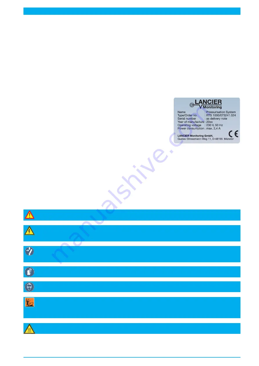
Marking
The pressurisation system is clearly marked by the content of the name
plate including technical specifications and manufacturer's instructions.
The name plate is found inside at the bottom of the cabinet.
The compressor on the mounting console is marked by the content of the
name plate including technical specifications and manufacturer's instruc-
tions. The name plate is found on the compressors housing.
Accompanying Documents
Documents delivered with this operating instructions are intended to assist for safe and secure operation of
the system.
• Certificate for savety valve and air storage tank
• A3 wiring diagram
• A3 circuit diagram
The system should be put into operation only if all documents have been read and understood by the operator.
Symbols used
Attention Danger!
This symbol warns of the health risks up to threatening injuries or death.
Warning Danger of electric voltage!
This symbol warns of the health risks up to threatening injuries or death
caused by electric voltage.
Turn power off!
This symbol indicates that electrical components and systems must be disconnected prior to
maintenance and repair work and also protected against resetting.
Wear protective gloves!
This symbol indicates that protective gloves must be worn during the works described.
Wear safety glasses!
This symbol indicates that safety glasses must be worn during the works described.
Note for disposal!
This symbol indicates that the resulting waste must be disposed ecologically and not become
domestic waste.
Risk of injury!
Take caution with heated components!
Содержание RTS 1000
Страница 15: ...Page 15 39 35 37 36 36 23 42 28 27 24 6 33 38 40 41 32 22 29 25 8...
Страница 21: ...Page 21...
Страница 47: ...Page 47 7 16 14 15 15 18 17 13 20 24 8 23 10 6 9 4 22 21 19 8...
Страница 51: ...Page 51 Pneumatics diagram Nr 074891 000...
Страница 53: ...Page 53 Circuit diagram Nr 074880 000...
Страница 55: ...Wiring diagram Nr 074881 000 Page 55...


