


5. Assemble drying agent container
• Insert new filter disc (
O
), PE sealing rings (
N
) and O-rings (
M
) in the
lower cover (
F
).
• Put cylinder tube (
H
) on the lower cover (
F
).
• Pour in new drying agent (molecular sieve) (
I
): approx. 500 g per drying agent container. Tap lightly on the
cylinder tube with the shaft of a hammer, to avoid cavity formation.
• Insert new filter disc (
K
) with lubricated sealing ring (
L
) in
the cylinder tube (
H
) and stand back from about 10mm
(see fig.).
• Place pressure spring (
J
) on the filter disc (
K
).
• Place PE sealing ring (
N
) and O-ring (
M
) in the upper cover
(
E
).
• Insert upper cover (
E
) on the cylinder tube (
H
) and tighten
with the nuts (
D
) as much as possible.
6. Remount drying agent container
• Insert and screw lower assembly bracket with the drying agent containers (
35
) again on back panel of
equipment.
• Screw all hose lines again onto the drying agent containers (
35
).
7. Check solenoid valves
Check solenoid valves (
36
) for proper operation and replace them at least after 8000 operational hours.
8. Replace double non-return valve (39)
Spare part order no.: 029814.000
9. Replace pressure limiting valve (38)
Spare part order no.: 029048.000
10. For the following operation start up the equipment again:
• Connecting hoses (
13
) are disconnected from air consumer.
• Close
shut-off valve (6)
.
• Connect power supply.
• Turn motor protective switch (
43
) to „I“.
11. Function testing
Carry out function testing, see pages 30 - 35.
12. Test impermeability
Test all hose connections of the whole system for impermeability.
13. After maintenance
• Open
shut-off valve (6)
.
Page 41
Содержание RTS 1000
Страница 15: ...Page 15 39 35 37 36 36 23 42 28 27 24 6 33 38 40 41 32 22 29 25 8...
Страница 21: ...Page 21...
Страница 47: ...Page 47 7 16 14 15 15 18 17 13 20 24 8 23 10 6 9 4 22 21 19 8...
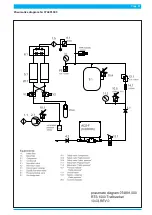
Страница 51: ...Page 51 Pneumatics diagram Nr 074891 000...
Страница 53: ...Page 53 Circuit diagram Nr 074880 000...
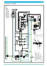
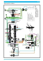
Страница 55: ...Wiring diagram Nr 074881 000 Page 55...


