Page 32
Check and set pressure monitor
Deadly risk!
Working on open, live equipment!
• Do not operate the equipment with damp hands!
• Caution: live components!
Risk of injury!
Wear protective goggles when opening safety valve „high pressure” (29)!
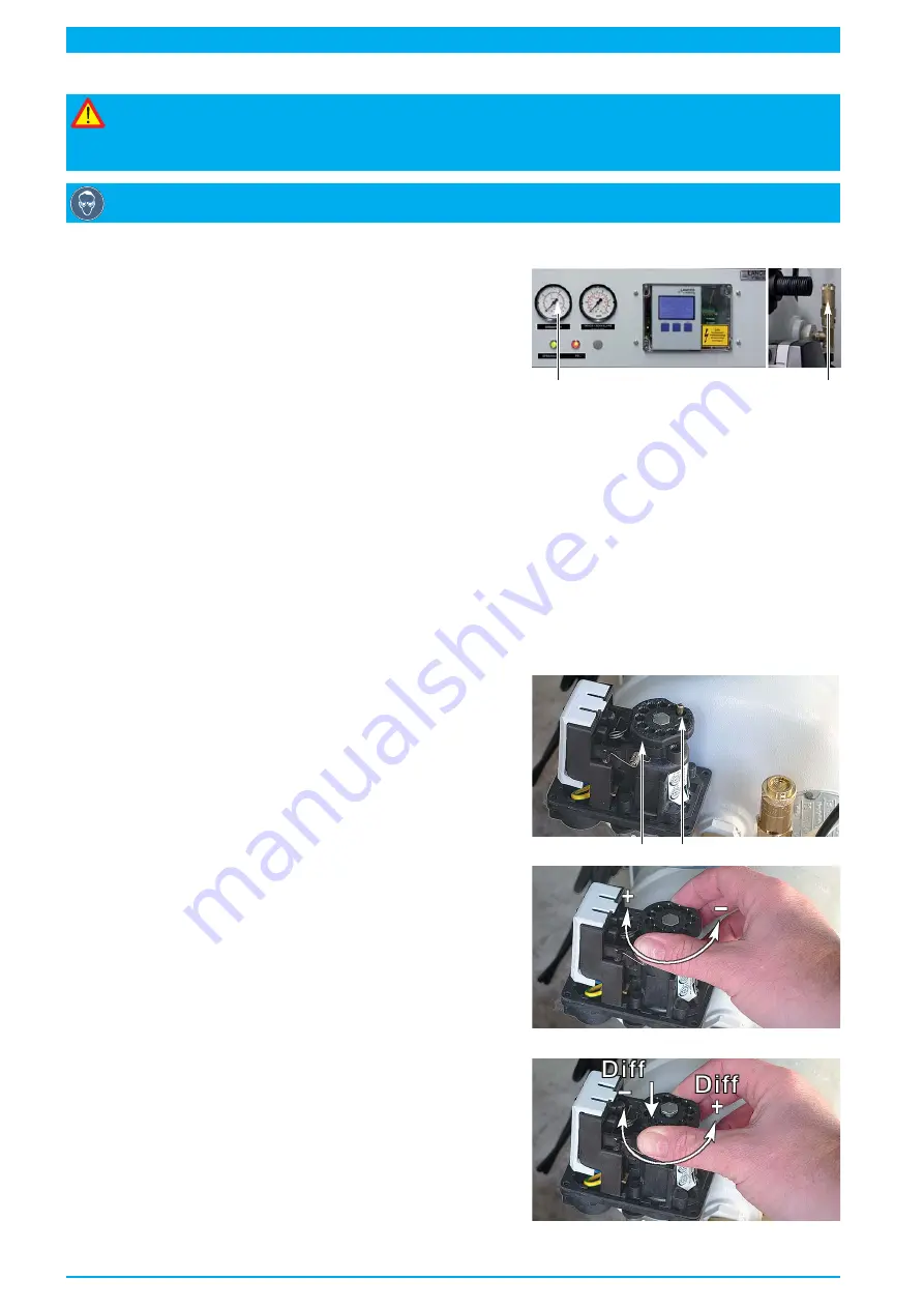
Setpoint value switching pressure
compressor
On
= 3.0 bar
Off = 5.0 bar
Check switch values
• Switch on motor protective switch (
43
).
• Close
shut-off valve (6)
.
•
Open safety valve "high pressure" (
29
) and observe
17
29
manometer "high pressure" (
17
).
- with a pressure drop below
3.0 bar
the compressor must start.
• Close safety valve "high pressure" (
29
) and observe manometer "high pressure" (
29
).
- with a pressure increase to
5.0
bar and furthermore the compressor must switch off.
To set the switch values note the following:
•
Only set pressure monitor (40) under pressure!
•
Rotating the hand valve (76) causes approx. 0.6 bar change of switching pressure.
•
First set the cut-out pressure and then the cut-in pressure, because changing the cut-out pressure
leads to a change in the cut-in pressure. This means the difference between cut-out and cut-in
pressure stays the same.
•
Once the hand valve has been pressed down (76) the cut-in pressure can be adjusted separately
and the difference between the cut-out and cut-in pressure changed.
Set the switch values
• Lift up the plastic cover of the pressure monitor after
unfastening the four screws.
• Unscrew the lock pin (
77
) of the hand valve (
76
).
Set the cut-out pressure:
Raise cut-out pressure
• Turn hand valve (
76
) clockwise (pr)
Lower cut-out pressure
• Turn hand valve (
76
) anti-clockwise (pressure -)
76
77
Set the cut-in pressure:
Raise cut-in pressure
• Press down hand valve (
76
) and then turn clockwise
(difference -)
Lower cut-in pressure
• Press down hand valve (
76
) and then turn anti-clockwise
(diff)
After setting
• Screw in lock pin (
77
) in one of the two retainers.
• Put on the cover of the pressure monitor again and tighten.
Содержание RTS 1000
Страница 15: ...Page 15 39 35 37 36 36 23 42 28 27 24 6 33 38 40 41 32 22 29 25 8...
Страница 21: ...Page 21...
Страница 47: ...Page 47 7 16 14 15 15 18 17 13 20 24 8 23 10 6 9 4 22 21 19 8...
Страница 51: ...Page 51 Pneumatics diagram Nr 074891 000...
Страница 53: ...Page 53 Circuit diagram Nr 074880 000...
Страница 55: ...Wiring diagram Nr 074881 000 Page 55...


