Page 28
Start-up
Deadly risk!
Do not operate the equipment with damp hands!
Take caution with live components!
Risk of injury!
Take caution with heated components!
Before start-up
The connecting hose is not yet connected to the consumer
load.
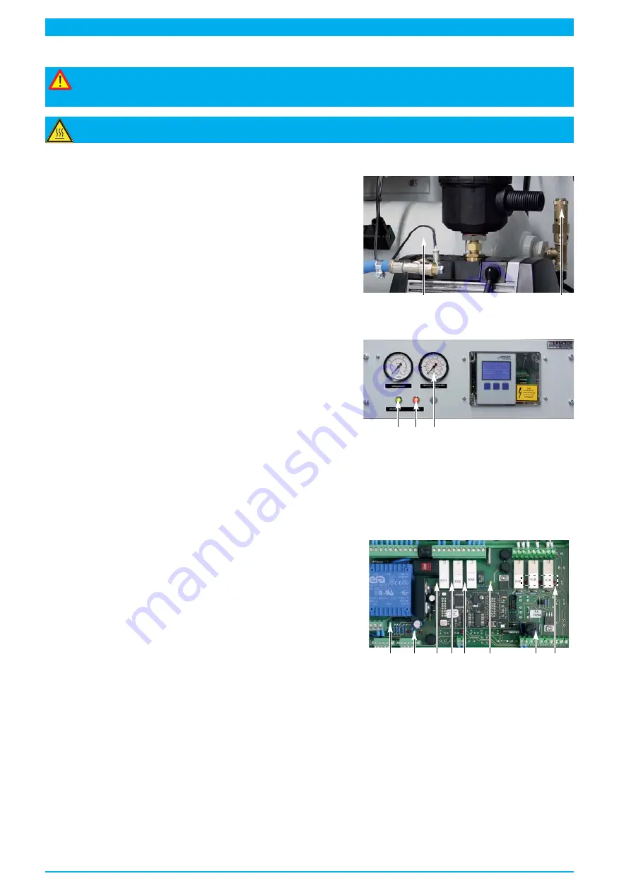
• Close safety valve "high pressure" (
29
) at air storage tank
(
28
).
• Close
shut-off valve (6)
.
28
29
Connect and activate main power.
Check indications of MFR (45)
• Green Signal-LED „
DC
“ (
47
) illuminates..
Check indications at the instrument panel (2)
• The green Signal-LED
„Operating voltage / Spänning”
(
19
) illuminates.
• The red Signal-LED
„Fault / Fel”
(
20
) illuminates.
19 20 17
Set the equipment into operation / charge equipment
Main power is connected and activated.
Turn motor protective switche (43) to "I".
• The compressor starts.
MFR (45) indicates at the same time
• The yellow Signal-LED „
State Comp in
“ (
57
) flashes.
• The yellow Signal-LED „
Comp OK
“ (
56
) illuminates.
• The green Signal-LED „
AC
“ (
50
) illuminates.
• The yellow Signal-LEDs (
58-60
) illuminate, after a short time
either LED „
Y1 state
“ (
54
) or LED „
Y2 state
“ (
55
) turns off
(cylinder-head ventilation of the compressor is completed).
• The green Signal-LED „
F-on
“ (
52
) illuminates (humidity moni-
toring is active).
50
52
54 55 56
57
4
7 58-60
Check indications at the instrument panel (2)
• The green Signal-LED
„Operating voltage / Spänning”
(
19
) illuminates.
• The red Signal-LED
„Fault / Fel”
(
20
) turns off.
Observe "high pressure" manometer (17)
• at 5.0 bar the compressor switch off.
• The yellow Signal-LED „
State Comp in
“ (
57
) in the MFR turns off.
Содержание RTS 1000
Страница 15: ...Page 15 39 35 37 36 36 23 42 28 27 24 6 33 38 40 41 32 22 29 25 8...
Страница 21: ...Page 21...
Страница 47: ...Page 47 7 16 14 15 15 18 17 13 20 24 8 23 10 6 9 4 22 21 19 8...
Страница 51: ...Page 51 Pneumatics diagram Nr 074891 000...
Страница 53: ...Page 53 Circuit diagram Nr 074880 000...
Страница 55: ...Wiring diagram Nr 074881 000 Page 55...


