19
CHECKS AND MAINTENANCE
●
Before starting up the boiler ask qualified personnel “LAMBORGHINI SERVICE” to check:
a)
that the data on the information plate corresponds to that required by the gas, electrical and water
supply networks;
b)
that the pipes which branch off from the boiler are lined with suitable thermally-insulated sheathing;
c)
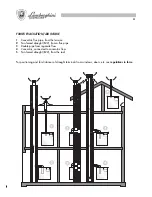
the proper functioning of the flue pipe;
d)
that the comburent air flow and the fumes evacuation take place properly in accordance with the
regulations in force;
e)
that correct aeration and maintenance are possible in case of installation in the furniture.
●
Ensure that the installer has connected the boiler safety discharge to a waste. In the case of the contrary
the intervention of the safety valves could flood the premises and the manufacturer would not be held
responsible for this.
●
Ensure that the piping of the installation is not used as an earth outlet for other installations; beyond not
being ideal for such a use it could in short bring serious damage to the other appliances connected to it.
●
Ask qualified personnel “LAMBORGHINI SERVICE” to check:
a)
the internal and external tightness of the gas system;
b)
that the gas delivery is that required by the boiler output;
c)
that the type of gas is suitable for the boiler;
d)
that the pressure of gas supply is within the values stated on the boiler plate;
e)
that the gas installation is the correct size and equipped with all the safety and checking devices
prescribed by the current regulations.
●
Ask periodically to check the proper functioning and the good state of the flue exhaust.
●
Ensure that the electrical system has been confirmed by qualified personnel to be adequate for the power
required by the appliance itself.
●
The electricity supply cable must not be replaced by the user, but by qualified personnel only.
●
The electrical safety of the appliance is attained only if the same has been connected to an effective system
earthed in accordance with the current regulations. The verification of this fundamental prerequisite should
be made by qualified persons as the manufacturer will not be responsible for damage caused by the lack
of adequate earthing of the installation.
38
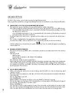
PROGRAMACIONES DEL INSTALADOR
Las operaciones descritas en este punto deben ser realizadas exclusivamente por personal capacitado.
La mala ejecución de las operaciones puede conllevar al mal funcionamiento o al daño del termostato
programador y de la caldera.
●
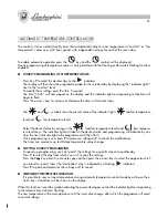
CONEXIÓN DE LA SONDA DE TEMPERATURA EXTERNA
El termostato programador puede gobernar una sonda para detectar la temperatura externa.
El valor de la temperatura externa utilizado por el termostato programador puede llegar de dos modos
diferentes:
-
cuando la sonda de la temperatura externa está conectada a la caldera la caldera envía el valor de
la temperatura al termostato programador.
-
cuando la sonda de la temperatura externa está conectada directamente al termostato programador,
éste adquiere y elabora directamente el valor.
Si estuvieran presentes dos sondas (ambiente y externa), se descarta la sonda ambiente y se utiliza la
sonda externa conectada en la base de la caldera; esta situación se indica además con el mensaje de
error
E67
.
Para conectar la sonda externa al termostato programador, utilice las conexiones S.EXT de la regleta de
bornes.
Con la sonda externa conectada el botón
visualiza el valor de la temperatura externa/tempera-
tura agua de calefacción.
●
ACTIVACIÓN REMOTA
El termostato programador cuenta con una entrada (identificada con
TEL +
y
-
) para permitir exclusivamente
la conexión de un programador opcional para la activación remota.
Modalidad de funcionamiento:
-
Entrada
TEL
abierta:
el termostato programador funciona como se describe en el presente manual.
-
Entrada
TEL
cerrada:
el termostato programador se prepara para uno de los siguientes funcionamientos:
calefacción y circ. sanitario activados y funcionamiento automático del regulador climático de acuerdo
al programa del temporizador, con las correspondientes visualizaciones en la pantalla; en la línea
de arriba de la pantalla se visualizará el mensaje
TEL
en lugar de la temperatura ambiente.
Esta modalidad de funcionamiento permanece hasta que el usuario desactiva dicha modalidad
(contacto
TEL
abierto) -actuando sobre el termostato programador para la activación remota-
restableciendo las condiciones normales de funcionamiento.
●
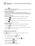
CORRECCIÓN DE LA VELOCIDAD DEL RELOJ
Con esta operación se puede corregir la precisión del reloj aumentando la velocidad, si el reloj se retrasa,
o disminuyéndola si el reloj se adelanta.
Durante toda la operación el termostato programador debe estar conectado a la caldera y debe estar
alimentado eléctricamente.
Corrección del reloj:
Presione y mantenga presionado el botón
R
Presione el botón
H/Day
Suelte el botón
R
y espere a que la pantalla visualice el mensaje de confirmación “
Hora
”.
Las dos operaciones siguientes deberán ser realizadas en 5 segundos: de no ser así el procedimiento será
anulado.
Suelte el botón
H/Day
.
Содержание thin 24 MCS W TOP U/IT
Страница 3: ......
Страница 5: ......
Страница 7: ......
Страница 9: ......
Страница 11: ......
Страница 13: ......
Страница 15: ......
Страница 17: ......
Страница 19: ......
Страница 21: ......
Страница 23: ......
Страница 25: ......
Страница 27: ......
Страница 29: ......
Страница 31: ......
Страница 33: ......
Страница 35: ......
Страница 37: ......
Страница 39: ......
Страница 41: ......
Страница 43: ......
Страница 45: ......
Страница 47: ......


