48
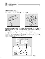
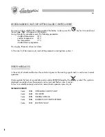
Once the connections have been made power up the boiler and, after the “
CON
” signal, check that the legend
“
OFF
” appears on the main display and that the time 00:00 on the lower display and the day indicator both
appear
.
If the legend “
CON
” persists this indicates improper connection of the control unit to the boiler.
NOTE:
In the event of a power failure the control unit will memorise the data for up to 24 hours.
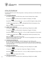
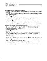
SETTING THE TIME/DAY OF THE WEEK
You can set the clock time and the day of the week in any mode.
To begin setting press the
H/Day
key once.
The minute figures will then start flashing.
Press the
+
and
–
keys to set the minutes and then press
H/Day
again to confirm.
The hour figures on the display will now flash.
Press the
+
and
–
keys to set the hour and then press
H/day
again to confirm.
Once you have completed setting the clock time the day indicator
will begin flashing.
The
indicators signal the sequence of days from Monday to Sunday (1 = Monday, 2 = Tuesday etc.)
Press the
+
and
–
keys to select the desired day then press
P
to memorise the settings.
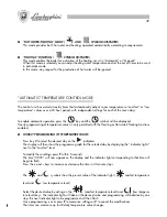
MODES
The control unit runs the boiler by enabling or disabling each individual mode according to requirements.
Press the
key repeatedly and the following modes will be enabled in sequence: OFF, Hot water, Hot
water/Heating and Heating.
●
OFF MODE (“OFF” APPEARS ON THE DISPLAY)
This mode allows you to disable the Hot water and Heating functions, yet keeps the boiler safety functions
operative.
In this mode any request for hot water and any request to switch on the heating circuit will be ignored.
●
“HOT WATER” MODE (
SYMBOL DISPLAYED)
This function enables the boiler for production of hot water.
When this function is enabled it is possible to adjust the hot water to the desired temperature.
In this mode, any request to switch on the heating circuit will be ignored.
89
ENCENDIDO
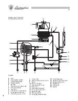
LLENADO DE LA INSTALACIÓN
Abrir lentamente el grifo de alimentación (
1
) hasta llevar la presión de la
instalación, indicada por el hidrómetro (
2
) al valor 1,5, a continuación volver
a cerrarlo. Verificar que la válvula de tres vías (
3
) esté en posición manual,
que la válvula de seguridad automática (
4
) situada en el circulador tenga el
capuchón aflojado y funcione normalmente, a continuación mediante una
válvula manual (
5
) situada en el calentador, hacer salir el eventual aire. Antes
del encendido, asegurarse de que la presión del agua en la instalación no
haya descendido por debajo del valor inicial de carga. Para un mejor
funcionamiento de la caldera mantener siempre la presión de la instalación
en valores no inferiores a 1,5 bar.
ENCENDIDO
Abrir el grifo del gas. Activar el interruptor general de alimentación eléctrica
situada en la pared. Seleccionar en el mando remoto la función deseada
(verano/invierno/apagado) visualizando la función con los específicos
indicadores.
INSTALACIÓN
Tiene que realizarla el personal técnico cualificado.
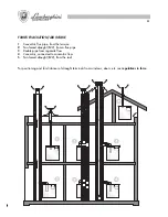
La instalación deberá ser conforme a las disposiciones de ley concernientes la evacuación de los productos de
la combustión según las NORMAS VIGENTES. Es obligatorio que la evacuación de los gases combustibles se
efectúe con tubo de diámetro no inferior al predispuesto en la caldera y que se empalme a un conducto de
humos, adecuado a la potencialidad de la instalación.
Les recordamos también algunos de los principales requisitos de unión entre los aparatos y los conductos de
humos:
a
) ser fácilmente desmontables;
b
) ser herméticos y de material adecuado para resistir a los productos de la combustión y a sus eventuales
condensaciones;
c
) no tener dispositivos de regulación (registros). Si tales dispositivos existieran ya, deberán ser eliminados;
d
) No debe sobresalir el interior del conducto de humos, hay que pararse antes de la cara interna de éste.
CONEXIÓN GAS
Efectúen la conexión del gas según la normativa vigente.
Hay que unir la caldera a la instalación con un tubo metálico rígido, o con tubo flexible de acero inoxidable
de pared continua y de tipo homologado. Los tubos flexibles metálicos ondulados hay que utilizarlos de
manera que su longitud, en condiciones de máxima extensión, no sea mayor de 2000 mm. Las calderas están
reguladas y probadas para funcionar con GAS NATURAL y GAS LÍQUIDO de la categoría II 2H3+, a una
presión nominal respectivamente de 20 mbar,28/30 mbar y 37 mbar.
PUESTA EN FUNCIONAMIENTO DE LA INSTALACIÓN
●
Procedan a la purga de aire.
●
Controlen que no haya escapes de gas (usen una solución
jabonosa o un producto equivalente).
Содержание thin 24 MCS W TOP U/IT
Страница 3: ......
Страница 5: ......
Страница 7: ......
Страница 9: ......
Страница 11: ......
Страница 13: ......
Страница 15: ......
Страница 17: ......
Страница 19: ......
Страница 21: ......
Страница 23: ......
Страница 25: ......
Страница 27: ......
Страница 29: ......
Страница 31: ......
Страница 33: ......
Страница 35: ......
Страница 37: ......
Страница 39: ......
Страница 41: ......
Страница 43: ......
Страница 45: ......
Страница 47: ......


