49
●
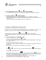
“HOT WATER/HEATING” MODE (
AND
SYMBOLS DISPLAYED)
This mode provides both hot water and heating, operated automatically according to requirements.
●
“HEATING” FUNCTION (
SYMBOL DISPLAYED)
This mode enables the boiler for activation of the heating circuit in “Automatic” or “Manual”.
When this mode is selected you can adjust heating water temperature and set the on/off times to be used
in automatic mode.
In this mode, any request for the production of hot water will be ignored.
“AUTOMATIC” TEMPERATURE CONTROL MODE
The control unit has a daily/weekly timer that automatically adjusts room temperature to “comfort” or “low
temperature” values over a 24 hour period, with independent settings for each of the seven days.
To enable automatic operation press the
key and the
symbol will be displayed.
Hourly programming of temperature values is only permitted with the Heating or Hot water/Heating functions
enabled.
●
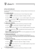
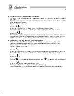
HOURLY PROGRAMMING OF TEMPERATURE VALUES
Press key
V
to select the desired day on the
indicators.
The display will then show the programme graph for the selected day by displaying the “indicator lights”
next to the “comfort” level.
To modify these settings press
P
within 5 seconds.
The time “00:00” will now appear on the display and the indicator light corresponding to that time will
begin to flash.
Press the
+
and
–
keys to increase or decrease the time in 30-minute steps.
The
and
symbols show the present value of the indicator light (
comfort temperature
level and
low temperature level)
Select the desired value by acting on the
(comfort temperature level) and
(low tempera-
ture level) keys. The indicator light will take on the desired value and programming will advance by one
step: the next indicator light to be programmed will then flash.
Once programming is over press
P
to memorise settings or
V
to cancel the modifications.
The timer can memorise up to 48 daily temperature value changes.
88
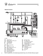
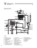
CIRCUITO HIDRÁULICO
DESCRIPCIÓN
A
GAS
B
SALIDA AGUA CALIENTE SA-
NITARIA
C
ENTRADA AGUA FRÍA
D
IDA INSTALACIÓN
E
RETORNO
1
Grifo de vaciado circ. sanita-
rio
2
Sonda circ. sanitario
3
Válvula gas
4
Acumulador instantáneo
5
Purgador manual del aire
6
Presóstato circ. sanitario
7
Válvula 3 vías
8
Presóstato falta de agua
9
Quemador
10
Intercambiador humos
11
Presóstato humos
12
Ventilador humos
13
Termostato de seguridad total
14
Purgador manual del aire
15
Vaso de expansión
16
Sonda circ. calefacción
17
Purgador automático del aire
18
Circulador
19
Grifo de vaciado circ.
calefacción
20
Válvula de seguridad circ.
calefacción
21
Hidrómetro
22
Grifo de llenado
23
By-Pass
Содержание thin 24 MCS W TOP U/IT
Страница 3: ......
Страница 5: ......
Страница 7: ......
Страница 9: ......
Страница 11: ......
Страница 13: ......
Страница 15: ......
Страница 17: ......
Страница 19: ......
Страница 21: ......
Страница 23: ......
Страница 25: ......
Страница 27: ......
Страница 29: ......
Страница 31: ......
Страница 33: ......
Страница 35: ......
Страница 37: ......
Страница 39: ......
Страница 41: ......
Страница 43: ......
Страница 45: ......
Страница 47: ......


