58
STARTING UP
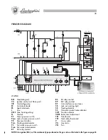
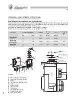
REFILLING INSTALLATION
Open the inlet cock (
1
) slowly until the system pressure indicated on the
hydrometer (
2
) reaches 1.5 bar, then close it. Check that the 3-way valve
(
3
) is in the manual position and that the automatic air purge valve (
4
) on
the circulator has its cap loosened and is functioning properly. Then vent
any air by means of the manual valve (
5
) on the boiler. Before ignition
make sure that water pressure has not dropped beneath the initial head
value.
For optimum boiler performance make sure that system pressure never
drops below 1.5 bar.
SWITCHING ON
Open the gas cock. Turn the main wall-mounted electrical power switch to
ON. Select the desired mode on the control unit (summer/winter/off),
using the indicator lights as a guide.
INSTALLATION
To be carried out by qualified personnel.
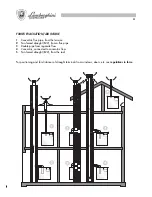
The installation must be in compliance with the stipulations of the law regarding the evacuation of combustion
materials according to the REGULATIONS IN FORCE.
It is compulsory that the gas fumes evacuation is effected with a pipe of a diameter not less than that required
by the boiler and that it comes connected to a flue pipe suitable for the capacity of the installation.
For connection of appliances to smoke conduits:
a
) they must be easy to dismantle;
b
) they must be sealed and of a material able to resist the products of combustion and their possible
condensation;
c
) they must not have regulation devices (gate valves). If such devices are already in operation they must be
eliminated;
d
) the connection itself must not project onto the inside of the flue pipe but stop before the internal face of the
same.
GAS CONNECTION
Carry out the gas connection in accordance with the regulations in force.
The boiler must be connected to the installation with a rigid metal pipe or a flexible stainless steel pipe with
continuous wall of the type approved. The flexible corrugated metal pipes must be installed in such a way that
their length, in a state of maximum extension, is not greater than 2000 mm. The boilers are calibrated and
tested to function with NATURAL GAS and LIQUID GAS, category II 2H3+, with rated pressure correspondant
respectively to 20 mbars, 28/30 mbars and 37 mbars.
SETTING THE INSTALLATION IN SERVICE
●
Proceed with the clearing out of air.
●
Check that there are not any gas leaks (use a soapy
solution or equivalent product).
79
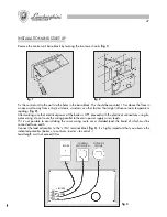
Una vez que se ha terminado de efectuar la conexión, encienda la caldera y después de que aparezca la
señal “
CON
” controle si aparece escrito “
OFF
” en la línea de arriba de la pantalla, la hora 00:00 en la línea
de abajo de la pantalla, y el indicador diario
.
Puede que persista la palabra “
CON
” lo cual indica que el termostato programador ha sido conectado a la
caldera incorrectamente.
NOTAS:
Si falla la alimentación eléctrica, el termostato programador puede mantener los datos establecidos
por un máximo de 24 horas.
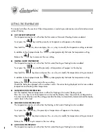
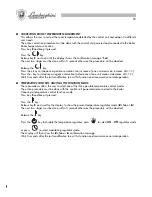
PROGRAMACIÓN DE LA HORA Y DEL DÍA DE LA SEMANA
Se puede programar la hora y el día de la semana en todos los modos de funcionamiento.
Para activar la programación presione una vez el botón
H/Day
.
En la pantalla empezarán a parpadear las cifras correspondientes a los minutos.
Presione los botones
+
y
–
para establecer los minutos y luego presione de nuevo el botón
H/Day
para confirmar.
En la pantalla empezarán a parpadear las cifras correspondientes a las horas.
Presione los botones
+
y
–
para establecer la hora y luego presione de nuevo el botón
H/Day
para confirmar.
Una vez finalizada la programación de la hora, empezará a parpadear el indicador del día
.
Los indicadores
indican de forma secuencial el día de la semana de lunes a domingo (1 = lunes, 2 =
martes, etc.).
Presione los botones
+
y
–
para establecer el día deseado y luego presione el botón
P
para memorizar todas
las programaciones.
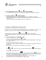
SELECCIÓN DE LAS FUNCIONES
El termostato programador gobierna el funcionamiento de la caldera activando o desactivando, de acuerdo
a las exigencias, cada función en particular.
Presionando varias veces el botón
, se activan en secuencia las funciones “OFF” – “circ. sanitario” – “circ.
sanitario/calefacción” – “calefacción”.
●
FUNCIÓN “OFF” (PALABRA “OFF” EN LA PANTALLA)
Esta función permite desactivar las funciones “circ. sanitario” y “calefacción” manteniendo activas sola-
mente las funciones de seguridad vinculadas a la caldera.
En este caso se ignoran la demanda de agua caliente sanitaria y la demanda de activación correspondiente
al circuito de calefacción.
●
FUNCIÓN “CIRC. SANITARIO” (SÍMBOLO
ENCENDIDO)
La función activa el funcionamiento de la caldera para la producción de agua caliente sanitaria.
Con esta función activada se puede regular la temperatura del agua sanitaria deseada.
En este caso se ignora la demanda de activación correspondiente al circuito de calefacción.
Содержание thin 24 MCS W TOP U/IT
Страница 3: ......
Страница 5: ......
Страница 7: ......
Страница 9: ......
Страница 11: ......
Страница 13: ......
Страница 15: ......
Страница 17: ......
Страница 19: ......
Страница 21: ......
Страница 23: ......
Страница 25: ......
Страница 27: ......
Страница 29: ......
Страница 31: ......
Страница 33: ......
Страница 35: ......
Страница 37: ......
Страница 39: ......
Страница 41: ......
Страница 43: ......
Страница 45: ......
Страница 47: ......


