


8
t1 = T / 2
t2 < 1 / (4 x fmax)
t3 = Monoflop time (see below)
n = Resolution in Bit
1/ fmax =< T =< 1 / fmin
fmin = min. SSI clock rate
(see data sheet)
fmax = max. SSI clock rate
(see data sheet)
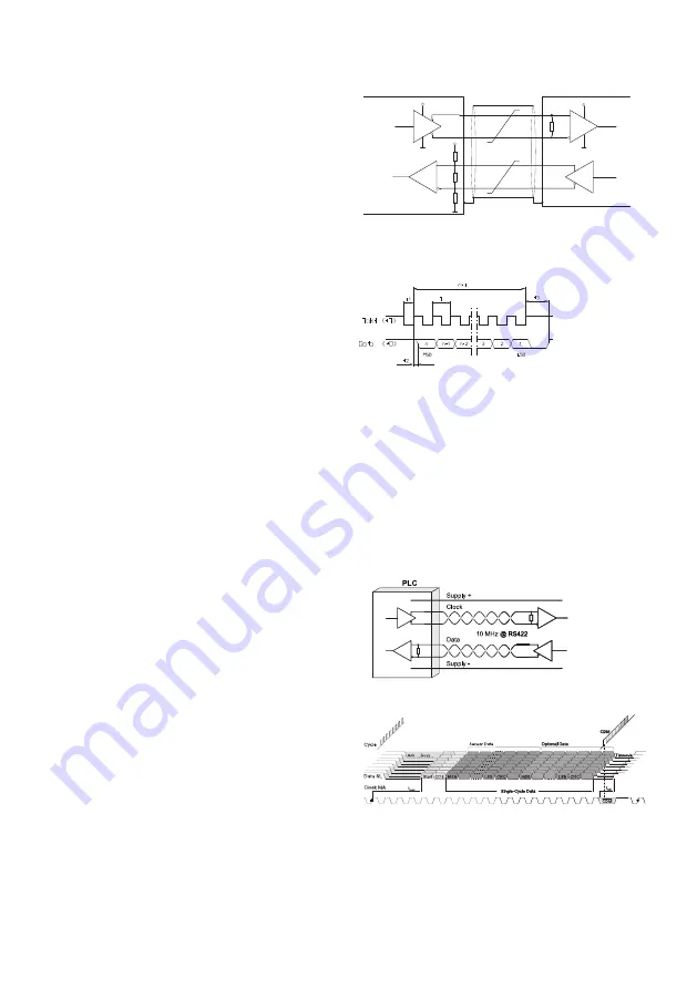
5.3 SSI - data transmission
The absolute position is transmitted via the SSI
interface to the controller as a digital data word.
The serial, differential transmission consists of
two clock lines and two data lines. The controller
sends clock pulses via the clock line and the
encoder supplies the position data via the data
line. A terminating resistor of 120 Ohm must be
connected to the data line at the controller input.
In the rest state, the clock and data lines are at a
high level. With the first falling clock-pulse edge,
the current encoder data are stored in the buffer
ready to be sent. With the next rising clock-pulse
edges the data are transmitted bit by bit, starting
with the MSB (Most Significant Bit). The transfer
of a complete data word requires n+1 rising
clock-pulse edges (n = resolution in Bit), e.g. 14
clock signals for a complete readout of a 13 bit
encoder. After the last positive clock-pulse edge
the data line will remain at a low level for the
period of the monoflop time t3 until the encoder
is again ready for a new data word. The clock
line must stay High for at least the same amount
of time, and can then again begin a new read-out
sequence of the encoder with the next falling
edge.
5.4 BISS-C-data transmission
The BiSS-C-Interface features bidirectional iso-
chronous communication between sensors,
actuators and industrial controls.
The purely digital link and its protocol has been
designed for maximum performance, transmis-
sion reliability and security.
Without affecting the payload data of measure-
ments or interfering with control cycles the com-
munication protocol incorporates a permanent,
bidirectional access to slave registers. That way
device parameters and additional measurement
data, or an electronic ID plate and OEM data,
can be accessed at any time.
For an unlimited subscriber count the interface
master provides the clock signal for simultane-
ously triggered actions. For an example, a typi-
cal RS422 link can support frame repetition
rates of 10 µs even with data words of up to
64 bits.
Z
RS485 Transceiver
+5V
+5V
Z
120
10k
10k
+5V
RS485 Transceiver
z.B. MAX 490
Z = 120 Ohm
Data +
Data -
Clock+
Clock -
RS485 Transceiver
e.g. MAX 490
Encoder
Control input
Data transmission is fully CRC secured for the
bidirectional command and register communica-
tion and for each single-cycle data channel
separately, with an assignation of a start value
ensuring channel identification by safety con-
trols.