
7: Options
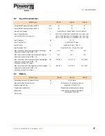
54
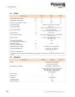
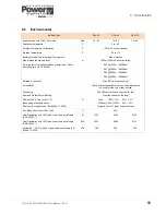
TS_619_00 PW9000DPA S2 User Manual 13/3/17
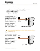
7.2.3 Battery temperature sensor
If required, the battery temperature monitor will be installed by the commissioning engineer.
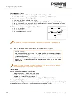
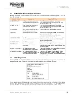
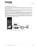
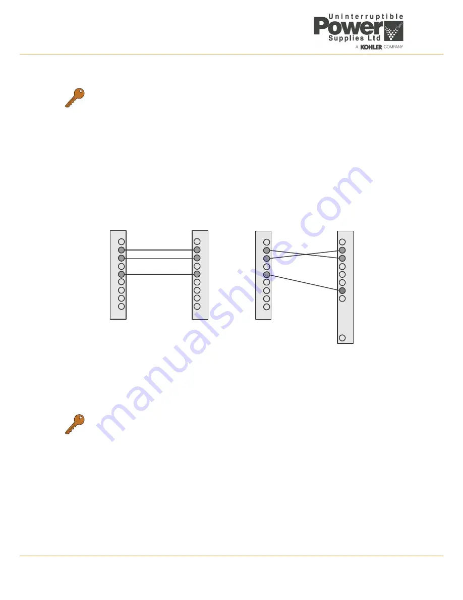
7.2.4 RS232 Computer serial interface – JD11 & USB
JD11 is an intelligent RS 232 serial port which allows the UPS cabinet to be connected to a computer for monitoring
purposes. Its connector is a 9-pin female D-type and it can be connected to a computer using standard computer serial
communications cable wired as shown below in Figure 7.4. The maximum length of the RS232 cable is 15m.
When used in conjunction with suitable software, this port allows the connected computer to continuously monitor the
input mains voltage and UPS status, and display a message if there any UPS system changes.
The USB port on the customer interface board is connected in parallel with JD11 and output the same data stream.
Figure 7.4 PC Serial port connector cable
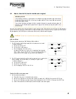
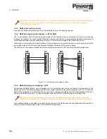
7.2.5 RS232 Interface for multidrop – JD12
The optional ‘Multidrop’ feature, which is available only in a parallel system, allows the customer interface board in the
master cabinet to collect data/messages from the other system cabinets via the cables connected to JD-12. The received
data is then processed at a centralised point on the ‘master’ customer interface board and made available to the user
directly on the RS232 port (JD1). It is also transmitted to the SNMP/CS141 card if inserted in the relevant slot.
If the multidrop feature is requested, the commissioning engineer will install the required kit of parts and test the system to
ensure it is fully functional as part of the UPS commissioning procedure.
Key Point:
In a parallel cabinet system only one remote shutdown switch is required, connected to the customer
interface board in the master cabinet. All the UPS cabinets will shut down when the remote emergency
shutdown switch is operated.
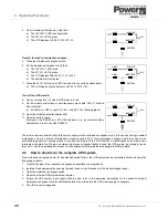
Key Point:
When the multidrop feature is used the I/O facilities of customer interface boards in the ‘slave’
cabinets are all disabled, but the customer interface board fitted to the ‘master’ cabinet remains fully functional.
1
2
3
4
5
9
1
2
3
4
5
9
9-
P
in
D
-T
yp
e
M
ale
9-
P
in
D
-T
yp
e
Female
UPS
PC
1
2
3
4
5
9
1
2
3
4
5
6
7
25
9-
P
in
D
-T
yp
e
M
ale
25-P
in
D
-T
yp
e
Female
UPS
PC
Содержание PowerWave 9000DPA S2
Страница 1: ...PowerWAVE 9000DPA S2 30 250 kVA User Manual ...
Страница 2: ...TS_619_00 PW9000DPA S2 User Manual 13 3 17 ...
Страница 8: ... IV TS_619_00 PW9000DPA S2 User Manual 13 3 17 ...